I'm stuck with a new build


JayC

TVWBB Fan
I built up the 4.2.4 board this morning and I think the soldering went well but now I'm not sure what is wrong.

I put the RPi board on, put the SD card in with the image already flashed on it and screwed the case from Tom shut. I then applied 12VDC to the HM and nothing happened (which also seemed like a good thing since no smoke came out).

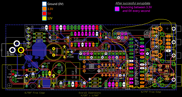
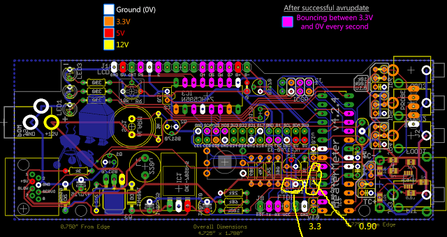
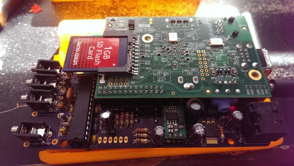
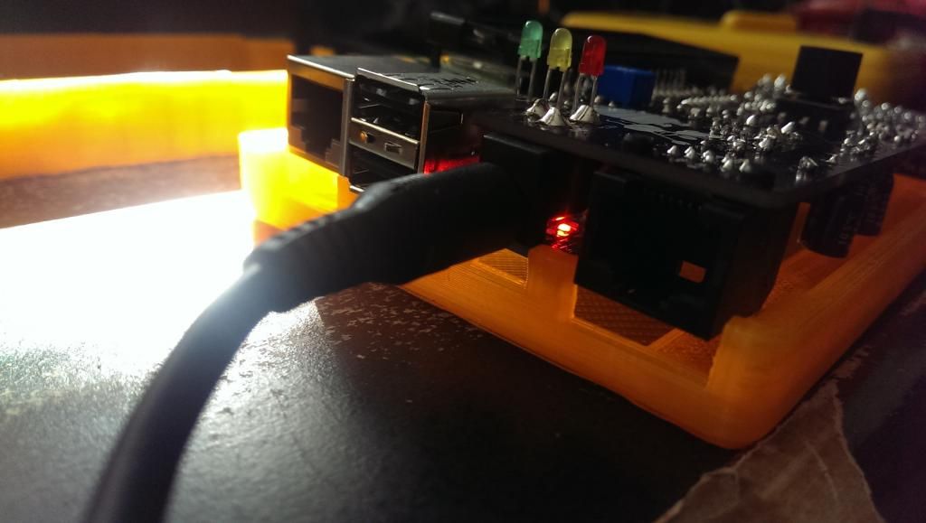
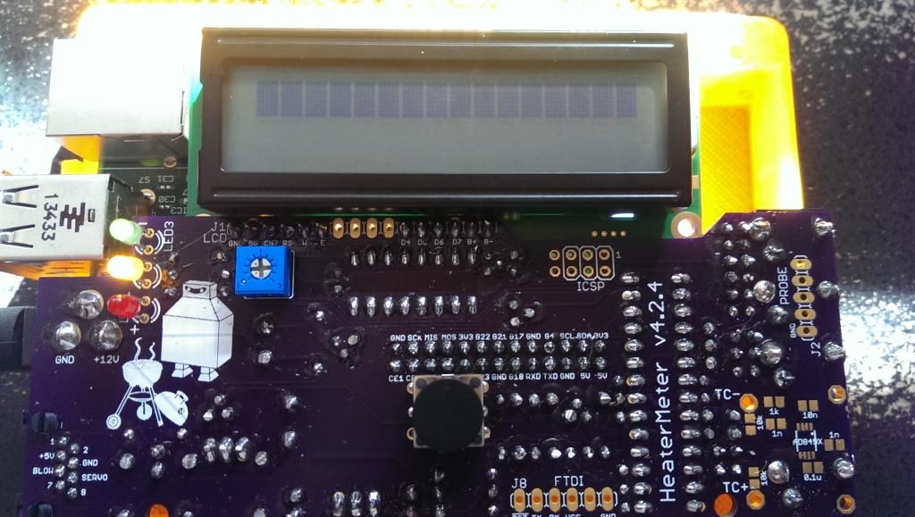
I took the case back apart with power on it and saw that the red LED on the RPi (B version) was lit. None of the LEDs on the HM were lit though. I adjusted the potentiometer so that the LED screen went full black, then backed it off and it didn't say anything on it still. (Pictures 1&2&3).

I let it sit there while we had lunch hoping that something might happen and it stayed the same.

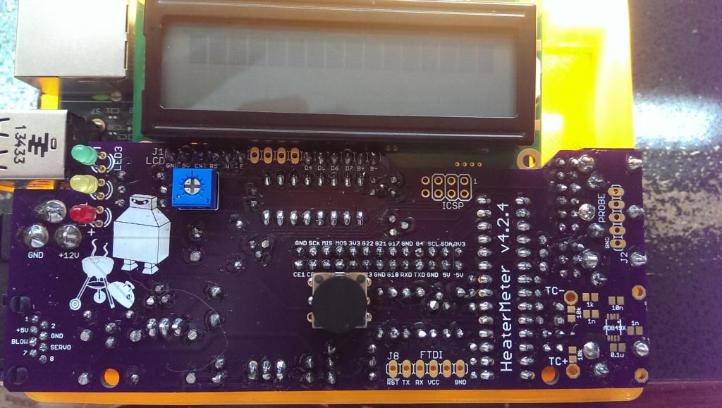
Finally, I uplugged, took the RPi off of it, put 12VDC back on the HM and started checking to see that I had 12VDC where I should and 5VDC in other spots but didn't do a super thorough checkout. Also, had a lit green and a lit yellow LED (though red was still not lit). I unplugged, plugged the RPi back on and applied power again. Now I have the LED on the RPi, the green and yellow on HM and a blank screen (Picture 4)

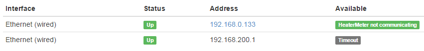
I hooked the RPi to to my router via a cable as I don't have a WiFi dongle yet. When I hit it with a browser, I can see two ports--I'm hoping that's a good thing but the fact that the HM is not communicating is probably a bad sign as well as the timeout (Picture 5)

Thanks for any advice you guys may have and thanks to all those that have worked so hard on this project.

Picture 1:
IMAG22211_zps278e26d9.jpg


Picture 2:
IMAG22231_zpsd45d717e.jpg


Picture 3:
IMAG22221_zpse2a0af67.jpg


Picture 4:
IMAG2224_zps5a6bf5be.jpg


Picture 5:
heatmeter_zpsd2a111c9.png
 
You start out by imaging the SD Card which builds the operating system for the rPi, but the ATMega on the HM is blank, and when your HM has a blank ATMega that's what you will see on the display. When you first boot the rPi/HM while connected together the rPi will try to communicate with the ATMega, when it sees a blank Mega it will flash it. After the ATMega is flashed and a quick reboot the HM should come to life and show "No Pit Probe" (whether connected to the rPi or not).

So it seems for an undetermined reason your Mega hasn't been flashed. So you need to work out why it hasn't been flashed, are the rPi and HM not communicating for some reason? Is there something wrong with the rPi loading the OS (memory incompatibility or something)? Problem with the HM build? Or maybe you just weren't patient enough on first boot to allow enough time for the rPi to load the OS and detect and flash the ATMega?
 
Ralph,

Thanks! Yes, I did put the image on the SD card on from my Windows machine to the SD using the Win32 Disk Image software so I should have gotten that part right (I'm used to doing this with Android phones during root/recovery install).

After probing some more, it appears that I'm not getting 3.3VDC on all of the board. I get all of it on the left hand side but no 3.3 in the section circled in yellow:

fubar_zps449fd94c.png


I'm guessing that may be a good hint for someone that knows what's going on at the board/component level. I only know enough to be dangerous.
 
Give the atmega chip another solid press to make sure it's fully seated into the socket.

Steve, I pushed and it snapped in just a bit deeper but not much. I'm still not getting 3.3V on the in that yellow circle though. The voltage comes up between 0.89-0.92 on all the 3.3V orange pads in the yellow circle. If I take out the ATMega, I don't get any voltage on the orange pads. Could I have a bad ATMega chip?
 
Pin(s) 7 & 20 on the ATMega are connected right to the 3.3v line... So make sure you have 3.3v on those pins, if not then you could pull the ATMega and check again to answer the "Could I have a bad ATMega chip?" question...
 
If you look at your HM board, the MCP1700-33 is your 3.3v regulator... A trace goes from the output side of that regulator on the bottom side of the board over to a resistor, on the top side of the board that resistor has a trace over to the capacitor next to it, which has a trace to the ATMega Pin7 on the bottom side of the board... So verify your 3.3v starting at the MCP1700-33 (and make sure you didn't put a BS170 MOSFET there by mistake?) then trace it to the resistor, capacitor, ATMega...
 
Last edited:
Jay, while this may not solve your problems, but looking at the pictures you posted, it looks like some of your components are only soldered on one side of the board. An example of this would be your LED's. Also noticed this on some resistors. Keep in mind that there are traces on both sides of the board. Just a thought, but it could be part of the problem. Picture 2 showing the component side of the board shows some resistors with the holes showing so that could be a clue. Good Luck.
 
If you look at your HM board, the MCP1700-33 is your 3.3v regulator... A trace goes from the output side of that regulator on the bottom side of the board over to a resistor, on the top side of the board that resistor has a trace over to the capacitor next to it, which has a trace to the ATMega Pin7 on the bottom side of the board... So verify your 3.3v starting at the MCP1700-33 (and make sure you didn't put a BS170 MOSFET there by mistake?) then trace it to the resistor, capacitor, ATMega...

Ok, Ralph. Now it's narrowed down. I have 3.3V at the MCP1700-33 (and I double checked and it's on flat side doward the capacitor like it's supposed to be) and I'm also getting 5V on the 5V pin too so it's working. I'm not sure which resistor your talking about but I think it's the 10k ohm 1% (blue body brown/black/black/orange/brown rings) that should have 3.3V on either side. Mine only has 0.90V on both sides. The capacitor just under the MCP1700-33 also has 3.3V on the one side as shown in this picture:

RalphRocks_zps794d23f0.png


Would that mean I have a bad 10k ohm resistor (as in I probably got it too hot when I soldered it)? I guess what I don't understand is that if the MCP1700-33 is putting out 3.3 and the resistor is bad why I wouldn't have 3.3 on one side and 0.90 on the other but I suppose that doesn't really matter if it's bad--just fix it huh?
 
Oh no! Yes, I was trying not to get them too hot as I didn't want to have any melted components. I'm sure that some of my stuff is only cleanly stuck on lead side and not also on the component side.
 
The area I circled in white on the image below shows the rather short path from the 3.3v regulator over to the ATMega...
3v.jpg

Orange pads from the left are 3.3v reg output over to the resistor, then on the other side of the board the resistor is jumpered over to the capacitor next to it, which back on the bottom side of the board the capacitor connects to the ATMega to provide 3.3v power.
 
RalphRocks_zps794d23f0.png


....why I wouldn't have 3.3 on one side and 0.90 on the other...

You noted 3.3v on the larger capacitor, which gets its 3.3v from a trace on the top side of the board. You noted .9v on the resistor by the ATMega which should have 3.3v, the trace that supplies the 3.3v to that resistor is on the bottom side of the board. So my guess is you need to resolder the output leg on your 3.3v regulator or look for a break/flaw in the trace that runs from the 3.3v regulator to the resistor...
 
Ok, so I hit all three legs of the 3.3v regulator and both sides of the resistor the blue resistor closest to the ATMega and both of the small 0.1 microfarad caps just to make sure that there was solder on both sides of the board on all of them. I'm not sure that the connection on the top side of the board made well as the caps are right against the board. Still, no changes. I have the ATMega out of the board and am looking for 3.3 on the 7th pad up from the bottom on the left as you have drawn there in your white bubble. In that white bubble, the only 3.3 I have is the output leg of the regulator. I'm assuming that means I have a bad trace on my board (or something else is wrong). Could I run a wire from the output of the ATMega to the top of the resistor to see if that changes voltages across the board or is that like crossing the streams to a proton pack?
 
Ah, well, even if you called I think Bill Murray would be pretty slow to respond these days... LOL

It does seem that trace between the 3.3v regulator and the resistor is your problem... Its that very short trace shown in red in the area I circled (*that SteveM traced out showing the combined path of both sides of the board). If there is 3.3v on the regulator side and not the resistor side.... I would think you could visually inspect the trace and find the problem, scrape a bit of the purple resist off the trace over the trouble area and flow solder across... but you can just put a jumper too....
 
Last edited:
Well, I have "no probes" now!

I was sort of disappointed right away when I plugged in probes from Maverick Redi Chek and still had "no probes". Then, I read that not all Maverick probes are created equally and I have the ET-732 probes with my current Maverick thermometer. I pulled them out a bit per what I found on the Wiki and now they are reading but not reading what I'd expect to see if they were reading correctly (probably because they aren't set up properly in the config). Regardless, I'll get some proper probes ordered and report back.

Thanks for all of the help. Hopefully the rest of what I did is working properly, time will tell. Thanks Steve, the continuity test just showed me that I was indeed not getting continuity from the first to second point. From the second point on were all good so I went with a wire from the 3.3 volt to the resistor and I'm all set. Thanks, Ralph for all the help.

WiFi and probes will be here mid week so I'll update you guys then.

Thanks again!
 
Congrats on getting it working...
Did you select the proper preset for your probe type in the Heater Meter Config?
 
Congrats on getting it working...
Did you select the proper preset for your probe type in the Heater Meter Config?

Hey, thank you guys for getting it working--I was just the helper I fell like.

I did not set the probe types (I did see it in the configuration though) as the ET-732 probes really don't work well without changing the resistors on the board from what the Wiki said. It's cool, that way I can keep the Redi Chek w/ ET-732 together and working and the HM will have it's own probes too. I can see still using the Redi Chek every now and then for shorter cooks and certainly for cooking in the oven.

I'm looking forward to getting the new probes and doing a test run.
 
Some of the problems with the ET-732 probes should have been eliminated with the addition of the RC filters on the HMv4.2... I don't think they will drop out at room temp like they used to but I haven't tried one on V4.2 yet myself. You've already figured out the plug can be a little longer and so you need to insert them MOST of the way (until you feel the notch). I wouldn't worry too much about the resistors, just set the config for ET-732 and they should work fairly well...
 
Some of the problems with the ET-732 probes should have been eliminated with the addition of the RC filters on the HMv4.2... I don't think they will drop out at room temp like they used to but I haven't tried one on V4.2 yet myself. You've already figured out the plug can be a little longer and so you need to insert them MOST of the way (until you feel the notch). I wouldn't worry too much about the resistors, just set the config for ET-732 and they should work fairly well...

Ralph, I found the details about the ET-732 AFTER I'd already monkeyed around with the Config tab and didn't realize it was simply a pull down option. I changed the settings and I'm reading temperatures on all four probes! To make things better, they all read almost exactly the same (will calibrate offset in boiling water after I get my new probes) AND I hooked up the fan and tested it in manual mode. So it looks like I'm set. What a relief! I was so worried I'd screw this thing up and it would be a technical nightmare to troubleshoot but it's working perfectly so far. I still have some new 72/73 probes coming and I'll change the settings and use those moving forward.

Thanks again for all the support from all of you! Now I'm thinking I should have bumped up to a thermocouple version (I was afraid and just trying to keep it simple). Maybe I'll build another one and keep this guy as a backup once I figure out that I can't live without it. I'll post pictures of everything functioning when I get it all hooked up to the BGE. I still have to fab something for the fan but that's the easy part for me. It's all this electronic wizardry that had me uncomfortable.


Back
Top