RalphTrimble
TVWBB Diamond Member
Yah, I noticed the odd angled top connection on the center tab too...
John - Thanks for validating this. I thought I'd done something wrong on OSH Park. It's a good thing I had a couple of spare boards lying around to check this on those because that extra trace to the ground plane was not visible with the OKI-78SR-5 mounted above it. I knew there was something wrong when I found such low resistance between 12V+ and ground at the power connector and then just continued to track through the board from there. The schematics were quite helpful.
BTW, this thing just looks so cool! Amazingly, that was really the only issue that arose. Everything else seems to be working fine so far now.
Board file is updated with the LED1 trace fixed. Pushed to github, shared on OSHPark and updated capnbry.net's HeaterMeter PCB.
I also nudged the 5V regulator up 0.01" to allow the ground plane trace to reach it directly. This may alleviate the need for the "white wire" ground fix.
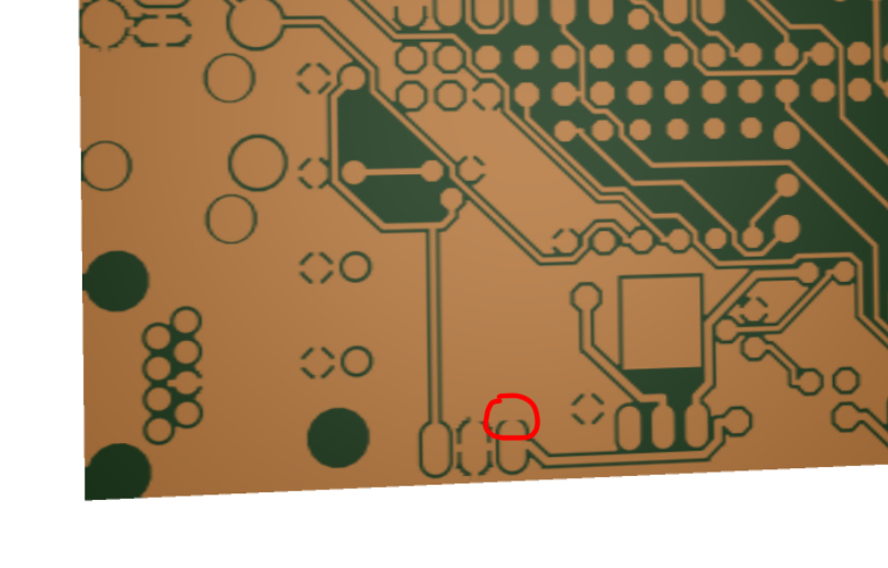
That's exactly what happened. I moved the other two traces but didn't see the ground one because it was part of the ground pour. Theoretically it shouldn't have shorted, it should have just come really really really close, but it is closer than the 6mil minimum clearance of the PCB fab.
New board file is on capnbry.net, or OSH Park, or github.
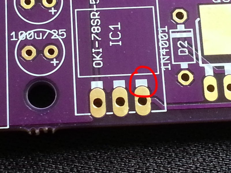
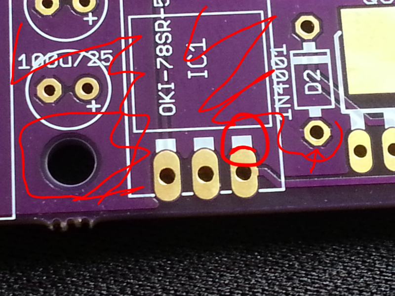
I got my 4.1.3 boards yesterday - all three are showing continuity between the 1st and 2nd pins. Before I begin surgery, is the culprit a connection under the white silkscreen? (circled on the right on Ralph's picture)
What's this little guy on my boards? Assuming a key chain?
