I finally got the SMD parts soldered, and now it would be time to test. However, I noticed that the board on the wiki is different, I guess it's the 4.2 board in these testing instructions: https://github.com/CapnBry/HeaterMeter/wiki/Thermocouple-Amplifier-Testing
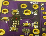
Mine is the 4.3:

Based on the different board layout, I cannot find the pins where I should apply power. My multimeter says the 5v pins on the board are not connected to any foot on the amp chip. Or at least there's no continuity from any of those, and I just cannot figure out what pins I should put voltage on, and I don't want to kill the chip with using wrong pins either...
4h of frustration with the SMD parts, it was quite a challenge to solder the amp on and get the pins free of extra solder. Would be great to get this tested and get on with the easier part...
Mine is the 4.3:
Based on the different board layout, I cannot find the pins where I should apply power. My multimeter says the 5v pins on the board are not connected to any foot on the amp chip. Or at least there's no continuity from any of those, and I just cannot figure out what pins I should put voltage on, and I don't want to kill the chip with using wrong pins either...
4h of frustration with the SMD parts, it was quite a challenge to solder the amp on and get the pins free of extra solder. Would be great to get this tested and get on with the easier part...
Last edited:

")