Heatmeter won't boot 12v will boot off PI power


Steve_I

New member
Hi just built my heat meter/Pi and connecting the 12v power nothing happens. I connected the PI's power and it booted up. I have verified the 12v power supply works by connecting it to the fan. I followed the instructions but there was one part I saw in the picture connected but did not see in the instructions the "MCP-1700-33" . I connected that. Should I have not used the MCP-1700-33, I see now it is a optional part for stand alone. If not that any suggestions on troubleshooting? I do have a volt meter but not a lot of knowledge on using it.
-
Steve
 
I removed the MCP-1700-33 after looking at a lot of pictures of the built units and not seeing it populated. I plugged in the 12v and it lit for a second then went dark. It still powers up via the PI. Not sure what to look at.
-
Steve
 
The first thing I'd check is that all of your solder connections look solid. Use a magnifying glass if you have one, or use a digital camera to take a closeup picture of the board and then looking at it zoomed in on a computer to see if you can spot things like potential solder bridges or other things.

After that, it's going to require using your mutli-meter to follow the voltage to see where it stops.
 
You should be able to leave the MCP1700-33 in there, I leave mine in all the time.

With the rPi attached and powered via 12V, here's some points to check with the voltmeter:
hmpi-power.png


The Pi doesn't power up at all connected to 12V? Seems like one of your diodes are backwards or the 5V regulator isn't in right or something else is backward pulling the power down too much.
 
Correct nothing powers up when I give it the 12v. I did use my volt meter on the power plug and get 12v reading. When I plug the 12v power in I have tried to read the power on the pins from the barrel connector at jp9 and not gotten any voltage. Am I doing something wrong or is it possible its the barrel connector that's bad? I have tried every combo of the 3 pins I soldered on and get no voltage there. I will try reading some of the points you indicated above.
-
Steve
 
Is the connection nice and snug or does it wiggle around when you plug in the 12v adapter? If it wiggles, try moving the plug around.
 
I tried testing some of the points above when connected to 12v and got nothing. I removed the 12v and powered it via the PI and when I tested some the above points I got the voltage you indicated. I think it's somewhere in the 12v path, damn I miss code to debug feel like such a noob in the real world electronics. Thanks again for all the help.
-
Steve
 
When I plug the 12v power in I have tried to read the power on the pins from the barrel connector at jp9 and not gotten any voltage. Am I doing something wrong or is it possible its the barrel connector that's bad? I have tried every combo of the 3 pins I soldered on and get no voltage there.
I've never seen one that is bad unless it was corroded, they're really simple inside, just 3 strips of metal. You could always try going around it using the +12V point on the blower connector and the GND point on the probe connector.
 
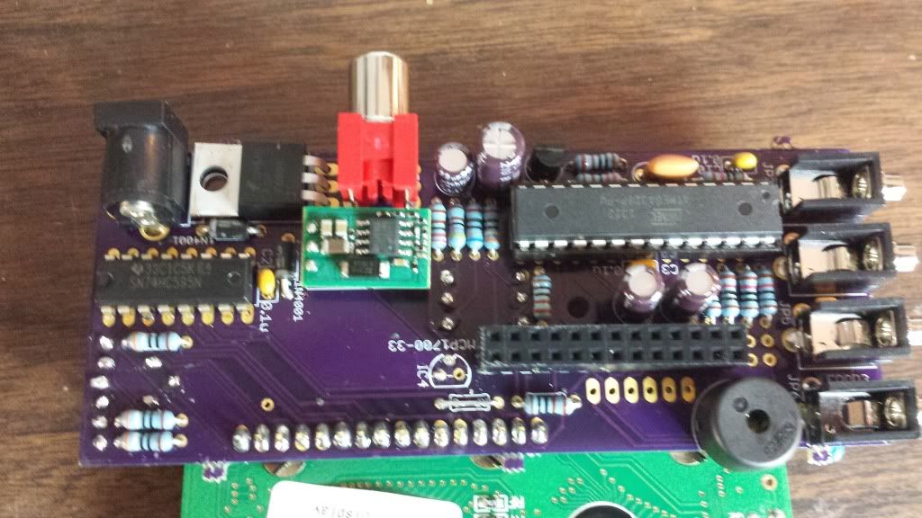
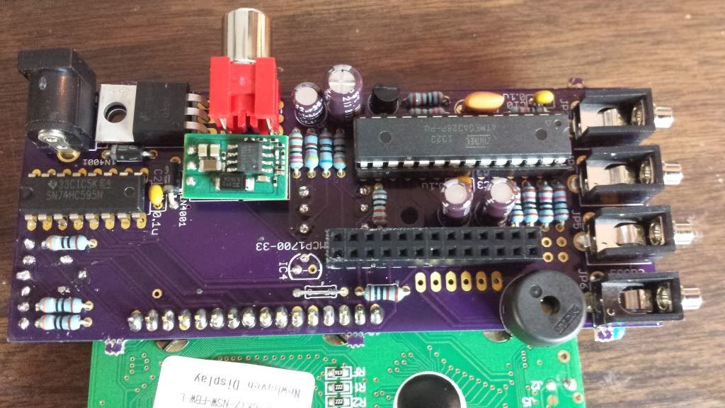
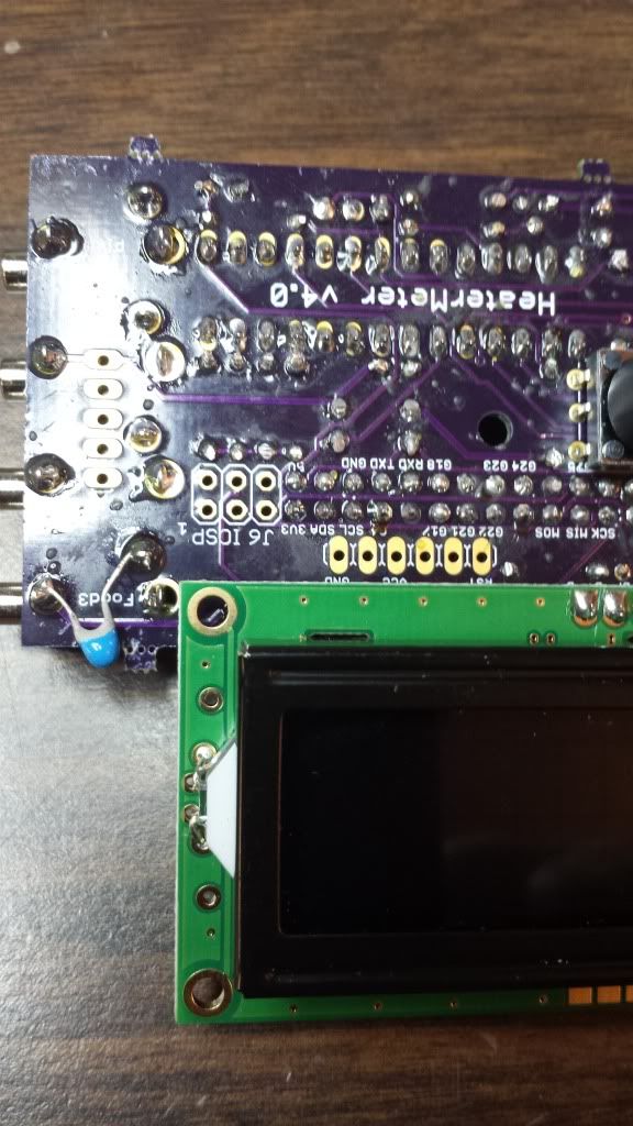
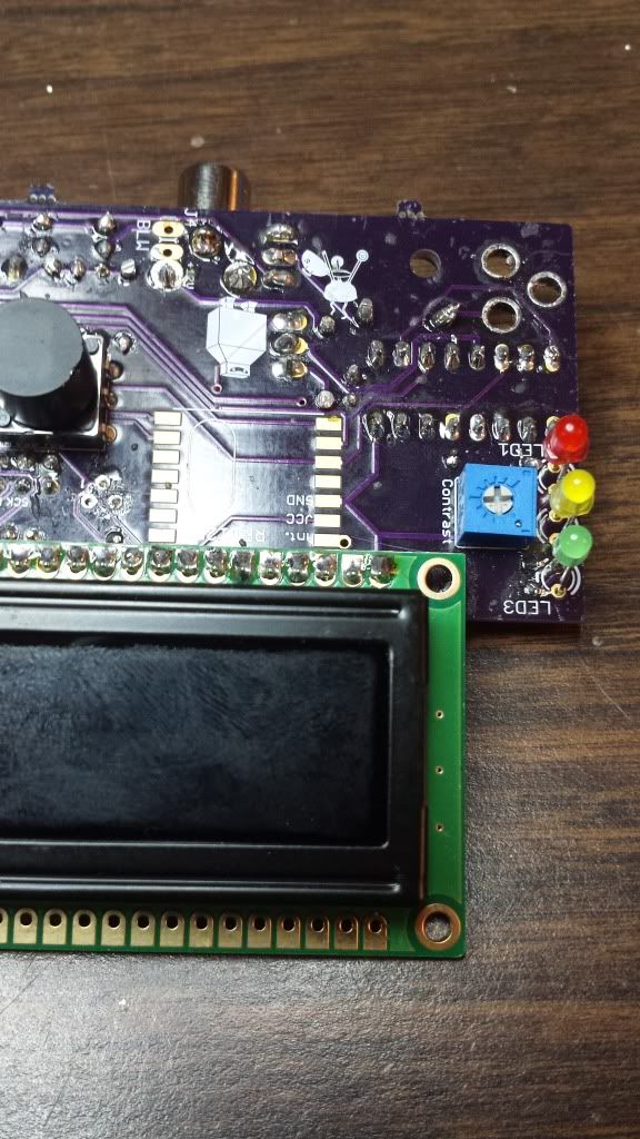
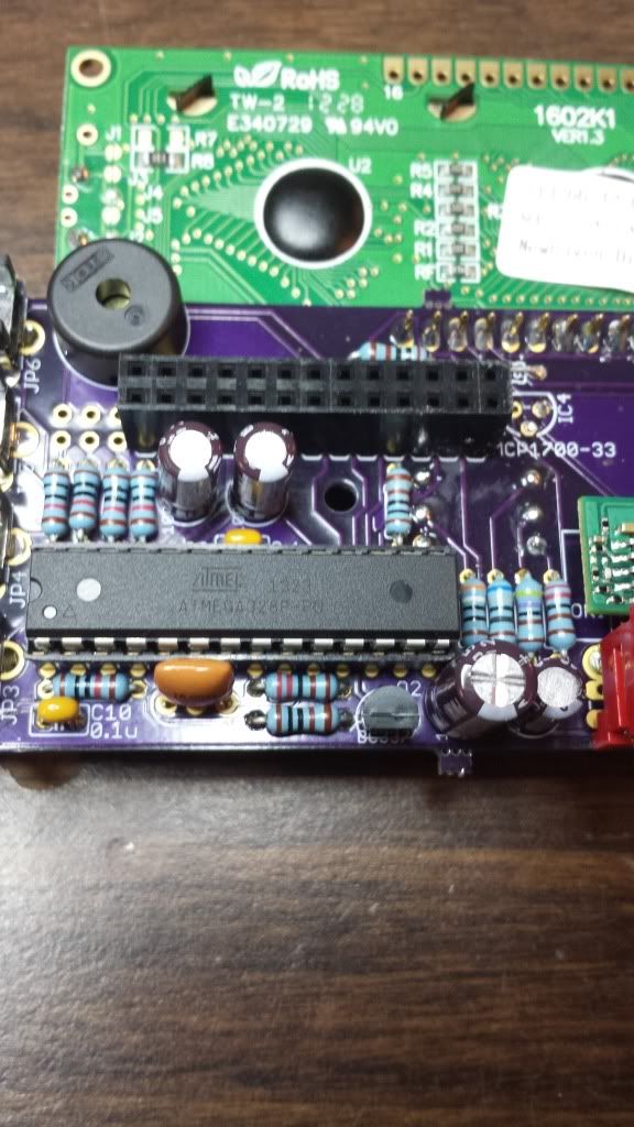
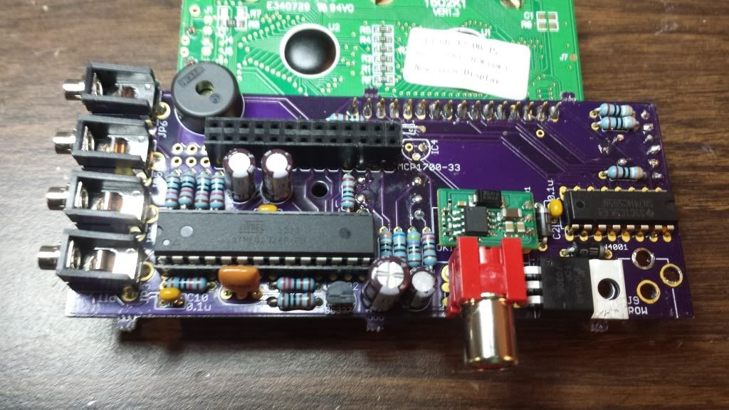
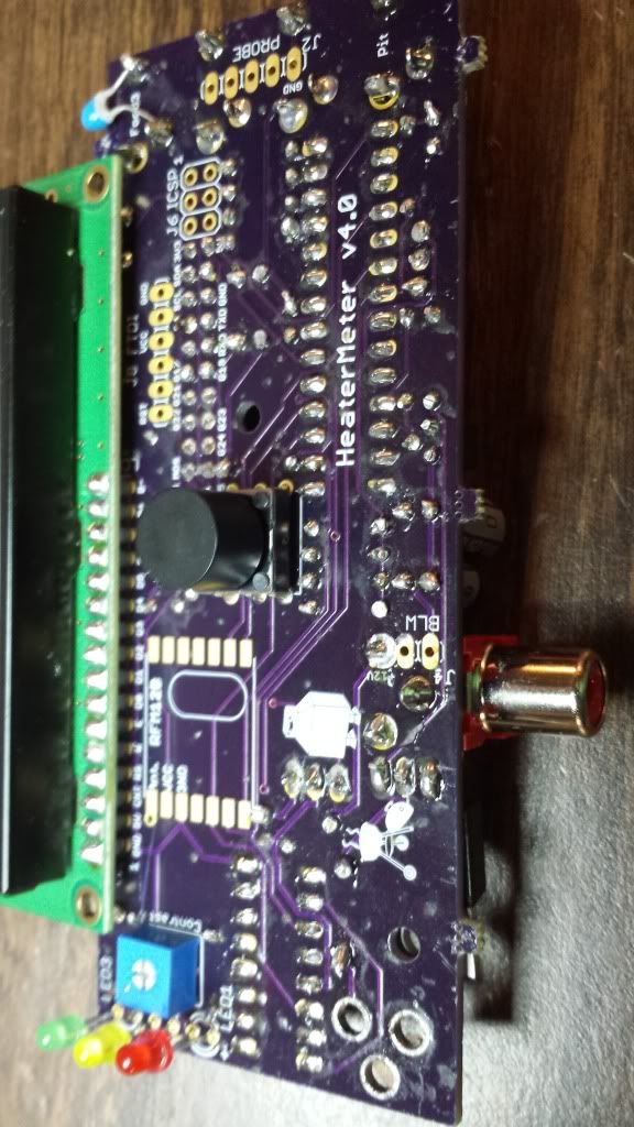
Ok I am hoping some pictures may help.


Oh and power connector fits snug have wiggled and twisted it to see if its getting good connection. Where on the board can I test for 12v or can I to see if it is getting the 12v?
-
Steve
 
I get no voltage between the 12v pin for blower and ground by probes. I am not getting voltage anywhere when I have the 12 plugged in, could that be a short somewhere? Or I got crap luck and got some component bad that is doing the 12v to 5v and 3.3v. I do see when I connect the PI's power everything functions, menu's probes etc so I must had soldered most of it correct.

Also again thanks all for the help.
-
Steve
 
Perhaps you have something installed backward or a solder bridge that is shorting the 12V to ground and the power supply is shutting down when plugged in? If you tap your meter across the two legs coming out of the power jack and there is not 12V there then either the jack isn't connecting to the PS or there is a short on your HM board. Hard to tell which is it from this side of the screen, but you could remove the power jack from the board and check for 12V out of circuit, if it is there then you have a short on board, if it is not you have a power connector problem.

I will take a quick look at your pics and comment back if I see anything note worthy.....
 
I looked over the board thru a 10x jewelers loupe and cannot see any solders that are touching or ones that don't look like good contact. I just expect I would get 12v somewhere on the board when connected even right at the jack, would a short or bad component give this kind of result. Sorry for my building like this knowledge is pretty basic, I've solder some wires and fixed one or 2 things on a circuit board before attempting this project. If it was a bugged program I would take it apart and test pieces of it but not sure how to do that for this. What does the 12v to 5v 3.3v conversion? Could I put that piece on a breadboard and test it somehow?
:confused:
-
Steve
 
Perhaps you have something installed backward or a solder bridge that is shorting the 12V to ground and the power supply is shutting down when plugged in? If you tap your meter across the two legs coming out of the power jack and there is not 12V there then either the jack isn't connecting to the PS or there is a short on your HM board. Hard to tell which is it from this side of the screen, but you could remove the power jack from the board and check for 12V out of circuit, if it is there then you have a short on board, if it is not you have a power connector problem.

I will take a quick look at your pics and comment back if I see anything note worthy.....

Thanks I was thinking of pulling the jack off first and test that will do that and see what I get.
-
Steve
 
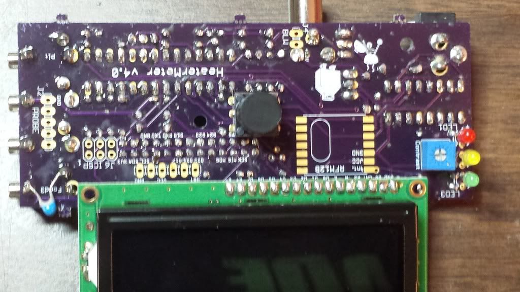
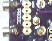
Unfortunately the picture of the solder side of your board is too blurry to zoom in and inspect the spaces between solder joints, a better picture would be more helpful. I seem to see a fair amount of stray solder on the board, so you might want to go over it and clean it up a bit. (The section near the probe and LED connections look like there could be issues in the photo) Either take a much clearer picture and zoom in on your computer to inspect for solder bridges (two nodes that are soldered together that should not be), or use a magnifying glass to look closer at the board to figure see solder that may be out of place. As far as I can see your diodes, transistors, IC's and capacitors seem to all be installed in the proper orientation...
 
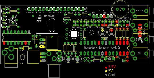
The power system in the HM is a little strange. 12VDC comes in through the power jack, that is converted over to 5VDC by the little circuit board regulator, that 5VDC powers the rPi, which in turn puts out 3.3VDC back to the HM board. This is why the 3.3V regulator is not needed when you use the rPi.

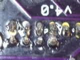
I just looked at the schematic and it seems the 12V is going to the fan and probes and the 5V regulator, the rest of the stuff seems to be running on 5V or 3.3V. It seems you may have a stray chunk of solder that could be bridging near the probe connections, hard to tell from the blurry pic but I zoomed in with the picture below to highlight the suspect area.....

SolderJoint.jpg
 
Last edited:
http://s1300.photobucket.com/user/stevei69/library/Heat%20MeterRemoved the power jack and tested it works fine I get 12v on my meter just on the jack. I agree must be a short somewhere. Besides visual inspection how can I search for it? Also looked by the probes I think that was some dust or something don't see it now. I took some new pics hopefully easier to see.


Full album
http://s1300.photobucket.com/user/stevei69/library/Heat%20Meter


BTW when connected power to PI I can connect probes and go thru menu's etc and all seems to work.
 
At first glance I would say look at the solder joints on the 4 resistors that connect to the probes, are they bridged over to the IC pins? I cant tell....
Solder2.jpg


I will keep looking, but since 12V is over on the probes I focused in there first.

BTW what kind of PS are you using? Is it possible its crapping out under load?

I think this is just the angle of the photo looking at it up close none are touching. I am using the psu from the parts link. 12v 1.0 amp. I have checked the voltage on the psu and its good, don't have another 12v psu beside maybe using an old PC psu and getting the 12v from that. The amps would be more would that be an issue?

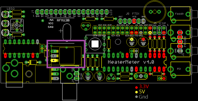
The below that I highlighted in purple is that the converter from 12v to 5v correct? And it gets 12v + from top lead, ground middle and bottom is output of 5v I am assuming. Could I remove this and test it, or is there any way to test for a short?

 
Yes, the circuit board where you have marked in purple is the 12V to 5V converter. Pin1 is the input(12V) Pin 3 is the output (5V/YELLOW) Pin 2 is GND(Gray)....

IDK what it reads like in circuit, if you measure a dead short between any of the pins I would pull it out of the board and then apply 12V to the HM board and see if you can measure 12V at that point.....
 
Last edited:


Back
Top