HeaterMeter Homebrew Controller


Thanks. Ill double check the specs but I'm running an uno. Can't wait to get it running with the smoker. Need to transfer to a board next. And find some food probes!
 
well, i'm in the final process of moving everything to a PCB. I just decided to use a arduino proto shield as it was actually the cheapest option. So far i've spent at least 8 hours. So tedious! A few lessons learned too. Keep double checking your layouts and fit to your case! I ended up with a few crossed wires to fix after an hour of testing all connections. Some how i ended up with an extra resistor on the button board too.

The one thing that's still happening and really driving me nuts is the LCD. When I plug it in the LCD just stays blank with the backlight on about 9/10 times. Sometimes hitting reset works, other times i just have to keep pluggin and unplugging. No clue what to do about this one. any ideas?

I'll post up some pics of everything once i'm done.

thanks!
 
I haven't been around much the past week so sorry I haven't responded to anything.

The way I have everything hooked up in my original HeaterMeter was that I plugged 12V into the barrel jack on the Arduino, then used the Arduino pins labeled "5V" to supply voltage for all my parts, then used the "Vin" pin as the fan supply voltage. The Vin runs through a diode so you only end up getting about 11V out, but that's close enough for the fan.

For getting coefficients for an unknown probe, the best app I've found for this is the Thermistor Lookup Table Generation Tool but the software "is currently being reviewed and updated." Luckily I still have my copy which I will share until someone sues me here. The automatic calculation functionality is still on the TODO list, so you'll have to manually measure temperature vs resistance and input it into the app.

The LCD not initializing is one of the problems I've never been able to reproduce but everyone else has experienced. There have been a couple fixes, assuming you've got it all wired up correctly:
-- Try replacing the signal diode with a rectifier diode. Replace the 1N914 with a 1N4001.
-- Try adding a drain resistor to the LCD data line. A 2.2k resistor attached from Arduino pin 4 to ground. This is easy to test without any soldering.

If neither of those work, check your connections yet again!
 
The Lcd seems to be sticking point for alot, including myself, of peoples problems.

See if touching, with your finger, pin #1 on the Atmega kicks starts it. I had and still do have that problem with the backlight will come on, but wont see any info until something on the Atmega changes and it decides to start working.

Im using the Router method from the other thread, and mine wont start until the router boots up and activates pin#1 on the Atmega. But, after I did Bryans recent update, it seems to be turning on sometimes right after I turn it on or the backlight will turn on without any info, just like what you describe.
 
I noticed while playing at my desk that after I plug it in via usb and it's not working, as soon as I open the serial monitor in arduino ide it kicks on. I have better luck using external power to have it turn on without issues. Doesn't always work, but often does.
 
I've done some quick upgrades to the windows application to work with the latest and greatest firmware from git. Since i don't have the ability to update it there, you can find my fork and get it from http://dev.bitbounce.ca/FogBug.../Group/Windows-devel

It adds com port enumeration and baud selection (must have device plugged in before starting app).

Allows setting temp, probe name and SHC values. Temp offsets can also be set. There is also a window that displays the serial information received.

It's still a work in progress and isn't anything fancy, but might help you out.
 
I can't tell what's different. Can you make a diff do a proper clone/modify/commit?

Originally posted by Mike Gravt:
It adds com port enumeration and baud selection (must have device plugged in before starting app).
Yeah that's the reason I left it as an edit box, so you could plug the device in after you've launched the app. I always forget to plug it in, launch the app, then get mad if I have to restart the app when it would have worked fine otherwise. If the setting isn't going to respond to hardware changes while running then it shouldn't be restrict input to an outdated list.

Anyway, you can probably tell that I wrote the whole app in about 15 minutes during my lunch break. It was meant to be just a quick way of verifying things were working more than anything else so it wasn't very pretty or optimal.
icon_smile.gif


Also your last two image links point to the same image. Is there one more image? "... Although there is a small glitch in the firmware I think... " I assure you, if there is anything wrong, it is in the hardware. I've been over that code 100 times with a fine-toothed comb. I'm a software guy so I know that works 100%. The hardware side, I know jack squat about so if there's a problem, that's where it is. Back when I didn't have the decoupling capacitor on the shift register, my display would go all wonky all the time. Turns out "everyone knows you need a decoupling capacitor" so the designs I was referencing omitted it assuming you knew it had to be there. There's probably something else like that happening caused by my ignorance of how basic circuits work.
 
yeah i should be able to do a patch diff. Same as you i'm just hitting it on my lunch breaks. Since i decided not to go with a linkmeter version i wanted to be able to do more over serial connection. I'll be updating to handle connect/disconnect and re-populating the list.

As far as the "glitch" I was referring to is that the fan doesn't pulse when under 10% anymore. The old firmware (r97) i think worked fine. But, i'm sure it could very well be the hardware as i probably know even less
icon_smile.gif


Currently i'm working on hacking my xoom tablet to support the ftdi usb module so i can connect to it... you know, just because
icon_smile.gif
 
Originally posted by Mike Gravt:
Currently i'm working on hacking my xoom tablet to support the ftdi usb module so i can connect to it... you know, just because
icon_smile.gif
Haha yeah I have a whole room in my house now becoming dedicated to "just because". I've got some solar garden lights I've got a half built RF node with a barometric pressure sensor in it. A new Black and Decker EM100B wireless power meter ($20 on eBay I can't help it!), a TI "launchpad" microcontroller, a TI FRAM evaluation board, 4 XBee radios... the list goes on and on. If only there were more time to write awesome software right?

I'll check out the fan pulse thing. I thought it was working when I used it last Sunday but I'm so hands off with the grill now, it might not be working. It does do 2s intervals now per 10s vs v97 now, so I know that's different. (It updates the fan speed only every 2 seconds out of the 10, so you're getting 2%/4%/6%/8% instead of the old 1-9%)
 
Yeah, i'm really getting into the "just because" this summer. Actually built a double 55 gallon barrel smoker, which is what this heatmeter project is being used for. Next, my dad wants me to do something for his greenhouse.

So, anyway, I've been looking for some probes and given I'm in canada, it was too expensive to order from the US. Anyone with a good price wanted double just to ship! So, i wondered into wal-mart today and picked up 3 "smart bbq" by jlr gear remote sensors.

I'm having a hell of a time getting the calibration right. The resistance at room temp is about 101.4k. I've found this link to help with the steinhart-hart calculations for the coefficients. It just never seems to be right. I've only been able to get stable resistance readings from room temp, fridge temp and boiling water. I just use the device that the probes came with to get the temperature reading for that resistance and plug it in.

I'm just wondering if there is something else i can try. Or do you have any thoughts on finding good set temperatures to use?
 
I posted it a few posts back but I just realized the link was broken. I use this to calculate my steinhart coefficients (for ambient thermistors).
http://capnbry.net/%7Ebmayland/fi/bbq/AN2395.zip

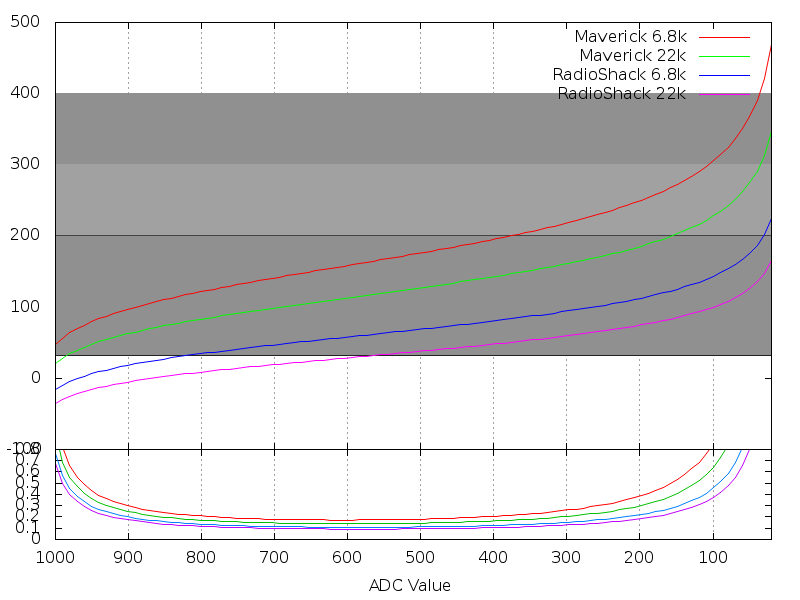
I'm wondering if maybe the boiling water isn't hot enough or maybe the formula doesn't work correctly. I've never tried getting things hot enough that they go past the plateau of the readings. Like from this image
steinhart.png

Does the formula account for where it turns upward after the long linear region? I'm not sure. The same method they use in the link above is the method I was planning to use for the LinkMeter software so I'm curious if it does.

I would think that it would at least be accurate over the temperature range you test though. If you have 3, maybe you can try putting 2 probes together (via tape or twist tie or something) then hanging them in the oven and plotting the resistance on one vs the temperature read on the other between 25C and say 200C?
 
Graph

Well that app really helped with being able to use a larger sample number.
What I ended up doing was taking readings every 2C while boiling water. I did this first as it's a much smoother temperature increase and a lot slower than using the oven. However, I had to switch to the oven to get higher readings. It was more difficult as the temp increased really fast. Also realize now how off my oven is. 170F was reading about 240! So anyway, I was only able to get temps every 3-4C with a "close" reading on the HIOKI.

From there i took a sample set evenly spaced and plugged it into the app and got my coefficients. Next, I set them in my heatmeter and repeated the test again. This time using the heatmeter for one probe and the remote reader for the other.

Just like magic everything was just about perfect! From a temp range of about room temp up to about 270F the readings were nearly exact, with only a 1F difference most of the time. Above that (i went to 300F) they started to be slightly more off, about 4F max, which given the graph above I would expect. I did the same on the opposite end by putting it in the freezer. At about 32F things started to be off more and more.

So, all said an done, i'm very excited now! I just have to repeat the process with one more probe that I'm using for my pit probe. I was thinking of using the third meat probe, but i find them to lag just a bit as the metal warms up. Might not be the end of the world, but i'm picky. Thanks for all the help!

Now, i have to figure out a way to attach the fan to the smoker! And hope it's big enough! I'm just using an old PC fan (DC Pico Ace 25).

And in case anyone else picks up the "Smart BBQ Remote Grill Temp Meter" the values I used are:

A=8.90063e-4
B=1.88136e-4
C=1.95173e-7

also fixed the LCD issue with a 2.2k resister from d4 to ground.

Also, oddly enough the fan pulsing is working. I've since re-programmed the unit, so who knows what happened.
 
Hey that's good news all around! Out of curiosity, which schematic did you use as your reference to build? The one linked on page one of this thread labeled BBQ-LCDHeader on 5/3/2011 or the schematic out of github from the eagle directory labeled LinkMeter from 6/11/2011?

I'm also curious to see how your computer fan works as a blower. Flat fans have much higher CFM than blower motors but blowers can work at higher static pressure. It will be interesting to see if it makes any difference in this application.

I came here to post because my Dad left his (original) HeaterMeter with me so I could install a U.FL connector and an antenna on his WiFi card. While I had it, I figured I'd replace his LCD, which he had cracked. It was functional except 8 pixels were dead. I had a spare NewHaven so what the hell right? Well guess what? Now his display only works if I put the multimeter or oscilloscope on D8. I've tried the 2.2K ohm resistor trick and got nothin. I think we've got the mother of all LCD problems here because I can't fix it without seeing what is wrong, and I can't see what is wrong because it fixes itself when you look at it!
 
yep, just working out a way to attach it all to the smoker now!

So anyway, I started with the schematic from the first page as you mentioned. But then added a resistor i noticed on the git schematic and then the second resistor for the LCD.

I actually re-drew the schematic in the fritzberg application so that i could do the virtual breadboard before trying it for real. Made it much cleaner i think. I have the files in my kiln repo. Although i haven't updated the added resistors yet. I dunno if you care to add it to the main repo or not.

I'll let you know how the setup goes. Going to use a small piece of aluminum sheet and a metal broom handle i found in the garage to rig up the fan.
 
Here is my test fan setup. You're right, the fan can't really handle the back pressure from the funneling. I actually feel more air coming out the back of the fan than the tube end. This was just a test setup to see how it worked.

I learned a few things, firstly, my pit runs much hotter than i thought. I actually thought it was running cool. I found my temps were overshooting to 250F ish without the fan being on. However, i cracked the lid just to check how the fan worked. I just don't think it's going to cut it. I need to change my setup and test some more though.

The other thing i notice is that i'm not going to be able to use the extra meat probe as the pit probe. It's too slow to cool down because of the "poker" holding the heat. The lid open will never automatically occur.

Here Is the attachment to my smoker. It's hard to tell from this angle, but there is a shot 2" pipe threaded into the bottom that i can run the probes through and attached the mount to. Just cut up a sink stopper for the end to keep the heat and smoke escaping.
 
Originally posted by Wm Hipple:
Use a hammer.....
It was driving me nuts. I mean I'm the guy that is supposed to be able to fix things and all along I've claimed "works for me", but bam there it was.

The crazy thing is that the LCD was working on my breadboard, using the same parts as was in HeaterMeter. Not only were they the same parts, they came from the same batch of parts ordered from Mouser. If there were any "exact same parts" this was it. The infuriating part was that measuring it made it work. The problem was clearly in the enable line though. I could measure from the Digital 8 (D8) line with no effect. What I eventually did was replace the 1N914 signal diode with a 1N4001 retifier diode and problem was solved. This is the same thing that worked for someone else. It is clearly the wrong part by all googling I can do, but it works.

Therefore I am recommending that everyone use a 1N4001 for the diode on the shift register (and will be posting a new schematic). It was what I used in my initial experimentation, it works, and you already need one for the fan freewheeling diode so might as well use the same part. I still need to test with an 74HC164 though.

Anyway Mike, love the quick fan mount! Maybe the solution is to... use a bigger fan! 80-92mm fans are in ready supply, and might push more cm of H2O right? (I mention this because you're doing what I wanted to try once I got time, using flat fans)
 
Hey guys, great job, and great reading. I am looking at starting this project and have read both the heatmeter and the linkmeter forums. I think I'd just like a heatmeter and have the hardware skills to build it, but am weak on the software side.

What I was wondering is, what functionality would I lose by using one of the available wifi shields( I have been watching ebay for a wishield for two weeks with no luck)?

Would the code port directly to the arduino blackdiamond and give me any basic web access without all the webserver code? Something like the other project, juse using wiserver? Or would I have to write new drivers and add flash or something.

thanks,
Adam


Back
Top