HeaterMeter Homebrew Controller


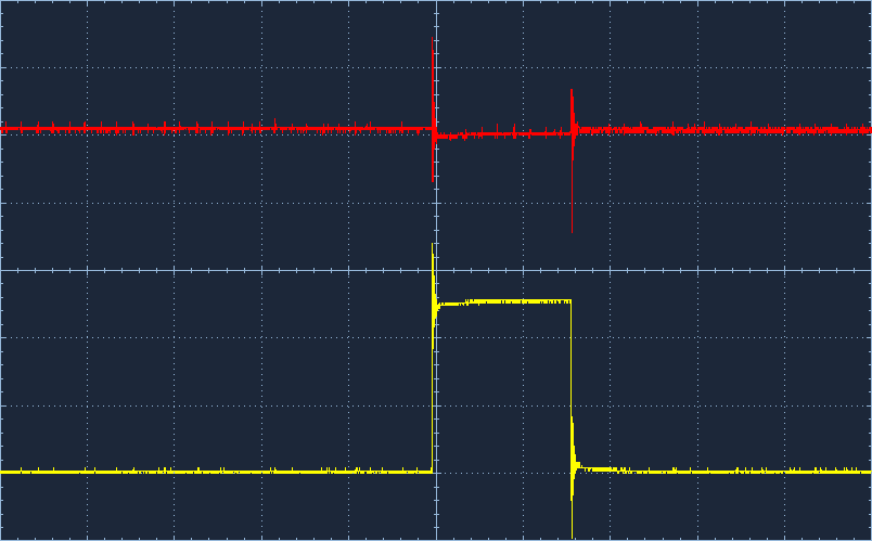
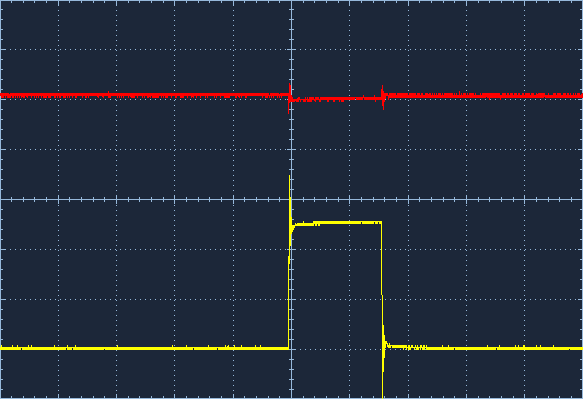
Yeah that blows my mind because it seems the 1N914 is the part for the job. They switch faster and have a lower forward voltage. In this case, the forward voltage is actually "remaining" voltage seen at the Enable pin on the LCD when we're trying to set logic low. So when we're trying to get 0V (not enabled) with an 1N4001, we actually are at 1.1V. That's one of the reasons I switched to the switching diode, that the "0" state was closer to 0.
EDIT: To clarify, this is when the LCDData is high but the shift register pin QH is low.

What's confusing to me is how it works for Ed and I but not for anyone else. Do we have MAGIC DIODES Ed?
 
I was just about to call it quits and now im going to have to try the 1n4001. I think Brian is right they must have some magical 1n914 because i have a ton of them and none of mine seem to work either, lol.
 
Originally posted by Ed Pinnell:
I wonder if that row that displays is trying to say that it is continually strobing without ANDing the logic, and that by using the other diode the level is changed to the degree that it is switching correctly?

Or it could have something to do with an assembly being greater than just the sum of its parts. Production tolerances and so forth...it just doesn't make sense to my feeble brain otherwise.

It would be interesting if Mike had an oscilloscope and wanted to investigate further...let's hope that this fix works for John, too. And John, I wouldn't hesitate to throw any of the general purpose 1N400x diodes in there...the worst that could happen is that it wouldn't work, which is what you have now.

The only other thing to do is to use a proper AND gate if the diode fix doesn't work for those people that continue to have problems. Let's hope this fix works!

I wish I (or Bryan) could get ahold of the components that aren't working and plug them into our setup and see if they work. My breadboard is still 95% set up..if not, we both have 'scopes...either of you guys want to exchange components via USPS? I'll send you a diode and shift reg that is working for me and you send me your parts that aren't working?

I do not have an oscilloscope, but I might be able to get access to one (but not in a timely manner).

My vote would be to use an actual AND gate, how much would the appropriate one cost from Mouser.

I would send you my diode and shift register via post. It will come down from Canada!
icon_smile.gif


LMK if you want to do that and your address, or if you want to send me your address off the forums.

MIke
 
Originally posted by Ed Pinnell:
Well, again, I am not an EE, so I hate to recommend something to someone else that I have not tried myself. I've gotten as far as finding that a 7408 (or 74F08) is a quad 2-input AND gate but I have not found an example of it being used in a circuit so I can't say if it will work without other supporting components.

We had some older Yushin parts-picking robots whose programmable controllers were composed of nothing but logic gates at one of the places that I worked for. We spent literally tens of hours troubleshooting these because they had to be online to track down when the error occurred. If it were me, I would have pulled the dozen or so ICs and socketed the whole shebang and whenever the things acted up, I would have just replaced all the chips, but that wasn't good enough for the guy in charge of the department...he had to know which chip was causing the problem. Nice story, I know, but maybe that's why I just can't get warmed up to doing this...I have other things that I want to do.

True, if the diode works, it works! As you said, hopefully John will be able to try the other diode as well so that we can see if I was a fluke or not.

Originally posted by Ed Pinnell:
It's another one of those "round tuit" things. It would be a simple matter to plug the components into my board and see if they work though, but it doesn't seem worth the hassle if you are not within the US, and if they didn't work I can't say that I would drop what I was doing to find out why.

Ok, makes sense.
 
Will give it a try this weekend. Hopefully it was my problem from the beginning as to why I have not been able to initialize the lcd screen.
 
If you bought the diodes from Mouser listed on the second post, I actually just ordered some from them a week ago because I had run out of my supply. I'll actually breadboard up a shift register LCD with one of those tonight and see if mine fails to work as well. Did you get that NewHaven LCD listed from Mouser too?
 
Originally posted by Bryan Mayland:
If you bought the diodes from Mouser listed on the second post, I actually just ordered some from them a week ago because I had run out of my supply. I'll actually breadboard up a shift register LCD with one of those tonight and see if mine fails to work as well. Did you get that NewHaven LCD listed from Mouser too?


Yes, I bought all my parts from Mouser using the links you provided in the second post.

Mike
 
The original 1N914s I had were from RadioShack and the waveform on the oscilloscope is identical to the 1N4148s linked on the parts list in the second post (I tested both). A ~950mV bump every time the LCD_DATA line goes high, and a 5V bump every time it actually enables.

With a 1N4001 it is sort jaggy and noisy at ~925mV and 5V but I'd think effectively the same. I'd love to show you the waveforms but my oscilloscope takes special USB cable that I can not find. I'll take some pictures once the sun goes down and the screen isn't so reflective.

Here's the deal on the breadboard. The gray wire is LCDDATA and the blue is the Enable line. The gray jumper may look like it goes to the same pin as the diode but the diode goes to 13 the gray goes to 14.
5bagF.jpg


I just realized in this circuit I have pin 2 of the shift register tied to high at all times but that shouldn't make a difference. Or does it? In the HeaterMeter itself, I have pins 1 and 2 just tied together connected to LCDDATA. I don't want to have to go and take another picture
icon_smile.gif
 
Weird! Not sure if this will reveal anything, but here is how my board is wired. I have the 1N4001 diode in there for this photo. The resistor looks like it is going to row 21, but it is the angle, it is going into row 20 with the diode.

Yours is much cleaner than mine, I didn't trim anything down.
icon_razz.gif


Breadboard.jpg
 
Originally posted by MPAClark:
Yours is much cleaner than mine, I didn't trim anything down.
Haha actually I just happened to have a couple pieces that were just the right size sitting in my spare parts bin from earlier experimentation. Most of my breadboarding has components mounted like 3 inches off the board in serious jeopardy of shorting the thing next to it at all times.

Your wiring looks fine (I mean obviously it is fine, it works!). It still is sort of baffling why the signal diode doesn't work but the rectifier diode does.
 
I finally found the oscilloscope cable. Here's the two different diodes in operation. The yellow is the clock pulse and the red is the voltage on the enable line.

1N4184 / 1N914
f5Sch.png


1N4001
u5BN6.png


As you can see, the switching diode I call for in the schematic produces the more accurate pulses, the value written is clearly 10110100. The 1N4001? I'm not really even sure if the secondary humps are 0s or not. In either case, both diodes should work because enable never goes over the threshold to become a 1 to the LCD until it actually goes to 5V.
 
It would work as a replacement for the WiShield but it has no dataflash chip (despite mentioning it once in the description). It also adds a LiPo charger circuit too, you'd think they'd mention that in the description. There's also some other mystery power chip, some sort of boost converter with a built in inductor? That seems implausible.

But yeah it should work to give you WiFi access but can't serve the HeaterMeter pages. You might be able to use an SD card over SPI to do that, if you're in to writing code.
 
writing code is what pays my bills, so I have no problem doing some of that, its the designing new circuits part that I would have an issue with, I am not very good at even reading schematics.

right now im attempting to decipher how to hook up the power to the 74ls164n chip it looks like you have C2 between VCC and GND but then the chip also attached so I don't understand what the C2 is doing
 
C2 is a decoupling capacitor. Without it, the supply voltage to the shift register drops every time the arduino sends it a pulse (red supply, yellow data):
spiketest-3pow.png


This was causing intermittent problems with the LCD getting garbled so standard 0.1uF ceramic decoupling capacitor is used to prevent voltage droop on the shift register:
spiketest-4both2.png


To hook up the shift register, run your standard +5V and GND to it on pins 7 and 14 and then place C2 somewhere close to the IC across the 5V and GND lines.

You can see it here on my LinkMeter sitting at the top of the IC. I just attached one leg to pin 14 there and then ran a small wire from there to ground.
 
oh I see so its like the power line attaches to the capacitor and then continues on to the IC.
that works, I have the lcd working with 2 wire on my breadboard, I used the 1N4001 Diode since it looked like there were issues with the other, now im working on laying it out on the perfboard.

question, your circuit on the perfboard looks so clean without any wires, are there wires underneath? or did you etch a circuit, I was planning on just running hookup wire underneath.
 
Oh yeah, there's plenty of wires underneath. There's even more now that I've added a RFM12B wireless module and a reset button.
linkmeter-2011042402.JPG
 
I am full of fail.. I was using I think 20 gauge hookup wires, and they are so thick and not very bendy that I am having a lot of trouble soldering them. after seeing yours I think I am either going to go get smaller wires.

or maybe just etch a design.
 
I feel for ya, man. I used 28 gauge wire with thick insulation for my original build and it was just a nightmare. My hookups were 22 gauge solid and they broke at the solder joints rather than bend. Now I use 30 gauge teflon-coated wire which is expensive as the dickens (like 70cents a ft) but is comparatively easy to work with. 28 gauge with thin insulation should probably be about right.


Back
Top