Jeff Baker
TVWBB Member
Any good resources or forums to look at?
Thanks for answering my questions.
Thanks for answering my questions.


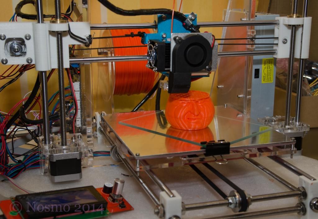
Anybody got an opinion on the daVinci 1.0 ? For $500, it looks like a good start. I've already found how to defeat the need for cartridges & how to put Repetier FW. I'd be willing to spend more to get more, but I don't think I could put together parts for 700 to do what the daVinci is capable of. Id still need to tinker, might as well start from a 'standard'
Talk me out of it.
I have one, you are correct the cartridges aren't as big a deal as everyone makes them out to be. For the most part they are cost effective with a cartridge being only $28 shipped from amazon prime. I too am running a hacked management software that doesn't even use the counters in them. There is a forum dedicated to it that has a hacked version of the software that allows you to load straight g-code from slic3r.
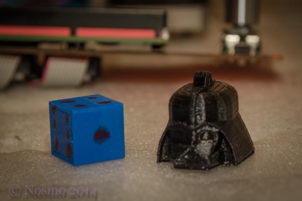
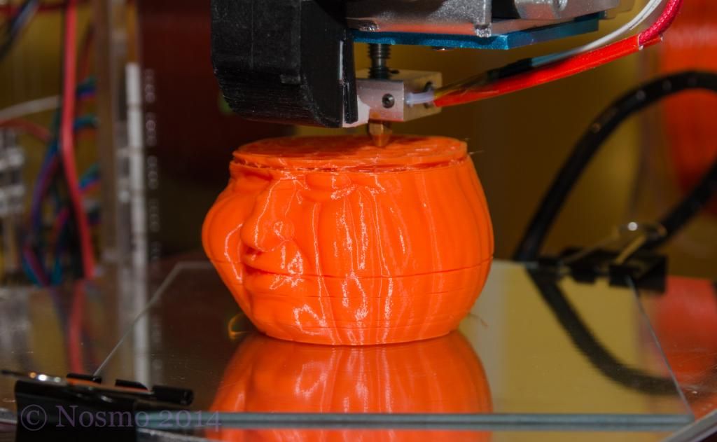
My complaint would be I can't get the thing to print accurate curves no mater what I try. The heater meter cases have been no problem, and random shaped things are fine. For instance there is a twisted star shaped vase 'demo' print built in that comes out great. However, if you want a precise circle or curve (I am currently prototyping my own damper system) it isn't accurate enough for what I want to do. This seems to be partly down to how belts work and the adjustments available for truing it up. And partly down to the plastic shrinking as it cools. The first problem makes it consistently off, which is why odd shaped things come out ok. The second is quite unpredictable and I have started experimenting with various starting and ongoing bed temps to try and address it.
Maybe my expectations for accuracy are too high, or maybe the problems I am having are just part of 3d printing. All in all, you probably can't beat the opening price for getting into 3d printing without having to build your own machine.
") )
)