General 3D Printing Thread


The pololu drivers are right there on the board, they just pull right out. I mounted my board in the stock location and was able to pull the pololu's and swap them without taking anything apart...

I feel your pain with the nut traps, I've come to realize they may be as painful as they sound... LOL

I know I've probably said it already too many times, but I am really happy with how firm the printer is with the base board and aluminum bed. I just tried to wiggle the single bearing end of the bed, solid as a rock! It used to do the hula!
 
Good point. I swapped the drivers and still can only get about 15mm/s stepper move on the extruder without it getting spazzed out. I ordered some more filament so I threw in an extra stepper just to see if it behaves much better. If so I'll swap it out. My bed was also clipping the front of the printer which every dozen layers would cause the Y to miss a step so I sanded it down until it cleared easily. Pretty big problem with this printer I'd say.

This morning I replaced my bed screws with stiff springs (haha that were only $6 at the time) M3-0.5 20mm bolts and M3 lock nuts. Much easier to level just turning a single screw rather than messing with the multiple nuts I was using. Even so my bed sags in the middle by almost 0.1mm:


So I grabbed some nylon stanoffs I had from Lowes and put them under the bed on the edges and cranked the edges down until it was more level:


Now I'm down to <0.05mm maximum error across the bed (switch error is <0.02mm). I also switched to using the Cura slicer because I like how it infills small areas in a smarter way rather than either leaving a gap or gobbing in too much extrusion. The source is also easy to modify and I've changed it to lay down a little more plastic on the bottom layer perimeters which helps with adhesion without making a mess of the solid infill. Doing a test print now at 60mm/s, 80mm/s infill. Looks perfect and it is almost done!
 
I'm gonna have to give the Cura slicer a try cause I am not completely satisfied with the way Slic3r works, thanks for noting that (I also found the infill on small areas to be lacking).
I"m glad you mentioned your bed smacking the y-idler, I KNEW it was a flaw in the design in general and not just a problem with my build. Like I said before, besides hitting the y-idler on the single bearing side I could see that the bed was dipping down in the center where the belt pulled on it, and the mount for the belt on the bed likes to work loose. I messed with the wooden bed too many times, shimming the bearings and the standoffs on the low end, making plastic bushings to minimize the amount of bite the bearings make on the soft wood. I finally got fed up and replaced the bed with an aluminum plate. I got a 9 X 12 X 3/16 aluminum plate on ebay for $10, cut the 12" side down to match the bed size, then mapped out the holes from the wooden bed and drilled. I tapped M3 threads into the holes where the mounting screws for the heated bed go and used stiff springs underneath the heated bed (local hardware stores seemed to not have a good selection of small compression springs, so I bought a spring assortment package from Home Depot which actually had several types of suitable springs in it, and to my surprise there were actually 4 of each, so that worked out well) This system worked out great because I can just turn the screws to level the bed (without having to hold a nut on the bottom) then I put a nut on from the bottom to lock them in place after it was all leveled. Worked like a charm, but I haven't done a ton of printing with it yet to see if it's gonna work loose. I also made printed bearing mounts that sandwich the bearings (top and bottom piece) which made it easy to mount the bearings to the aluminum bed using just two holes rather than a slot like the original bed. This pulled the bed up over the y-idler a few mm and I will never have to worry about it smacking there again. I put nut traps on the lower bearing mounts so I can just turn the screws from the top to tighten them, which allowed me to tighten the bed to the bearings just right so they are secure but not too tight and binding. My bed is now rock solid, flat, level, moves super smooth and easy and will never hit the y-idler again, and it is easy to remove and adjust, huge improvement for only a couple bucks. I would suggest you consider doing the same with your printer, IMHO the wooden bed is too thin and flexible and the slotted bearing mounts are for the birds.....
I'm kinda surprised about the limited speed from your extruder stepper, mine will spin much faster before it craps out. Hope your replacement stepper spins faster for you.....
I'm pretty happy with the printer now, the bed and frame are really solid (with the frame screwed down to a base). However, I think the extruder is still a little too flexible with the wooden mounts so I can see down the road replacing the wooden parts with some printed parts which I think will be more rigid. Not sure yet if I will have to design the parts myself, or perhaps there is already a printable extruder design available that will work with linear bearings? That will probably be my next mod.
Also the z end stop leaves a bit to be desired. I recall you replaced the switch with an opto sensor, how is that working out for you?
 
I've put the modified Python script I used for leveling my bed on my Google Drive mendel-bed-mapper-M114.zip. The UI is pretty rough but once you figure it out it works pretty well. Requirements are listed in the Readme and is directly descended from mendel-bed-mapper

Where's the pictures of your supercool bed, Ralph? I want to see it!

I really like the optical endstop. It is less of an endstop and more of a position finder. With the switch-based endstop, you have to adjust it so the switch just triggers as when the head is in exactly the right place on the bed. With the opto-endstop, the endstop triggers before the head gets to the bed, but because you can actually pass completely through, you can set the Z programmatically rather than trying to get a screw juuuuuuuust right.

My printer homes Z then does this in the startup GCode
Code:
G1 Z-2.56 F200 ; move down 2.56mm to just kiss the bed
G92 Z0 ; set this as Z=0.00

It also has pretty good repeatability because you're not dealing with a mechanical switch that will have bounce characteristics. The opto endstop has a sharp voltage drop as something starts to pass through the interrupter which registers as triggered when it falls below the ATmega's "LOW" threshold. Running a test of homing the Z, then moving up 5mm then back down until it hits the endstop 100x, I see a standard deviation of 0.00537mm.
 
Thanks for the info on the optical end stop and bed leveling script, I will have to look into giving them both a try.

Sorry I didn't post pics of my new aluminum bed, I didnt take pictures of it when I was building and now that it is assembled you can't really see it with the heated bed on top. That's why I was a bit verbose in the description, I think I did a fair job describing what I did and what I used to do it... (12 X 9 X 3/16 Aluminum plate from Ebay, Compression spring assortment from Home Depot, and an M3 tap which I had to buy a tap assortment from Home Depot to get because all the stores only seem to go down to M4 tap when sold individually)

I just snapped a few pics of my printer to highlight the mods I did....

bed.jpg

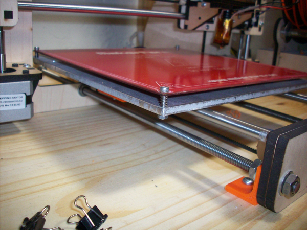
Above you can see the aluminum bed, the M3 cap screws are threaded into the bed and then locked in place with the nut(s) below. You can also see the mounting bracket I made to secure the Y-idler to the wooden base (I used a bracket on both threaded rods) You can't see the belt, but I used a couple pieces cut from a 1" aluminum L-channel to connect the belt to the bed.

BearingBushings.jpg

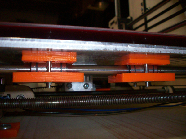
Above you can see the bushings I made to mount the linear bearings to the bed. They are hollowed to hug the bearings and the bottom part has nut traps so you don't have to hold them from the bottom while you tighten from the top. They will mount to the bed with just two holes, no slot required. If you would like the files for these parts just let me know if you want the 123D, STL or G-code version. They are not prefect, I quit working on them when they were close enough to work. (the nut traps are very close to the outer edge, because the lower bushing must be very slim to avoid hitting the y-motor in the back)

brackets.jpg

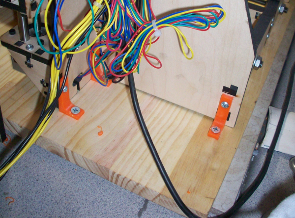
Above you can see the L-brackets I printed to mount the frame to the base. I used 3 on each side mounted to the frame with the existing frame screws and wood screws securing them to the base. I used three brackets on each side of the printer.

Before I did these mods if I wiggled the Z-tower the frame and extruder would move like crazy, if I watch the hotend at the bed the movement was very pronounced. Now the frame is pretty solid and if it moves at all the entire printer moves as a unit. Before I made the aluminum bed if I put a tiny bit of pressure on the end of the bed it would move quite easily, specially on the single bearing side. Now the bed is rock solid, it takes a whole lot of pressure to make it move a tiny bit.

At this point the mechanical switch on the Z-end stop and the slightly flexible wooden extruder mount are my weak points. I will be trying out the optical end stop for the Z-Axis soon and am looking for a printable extruder mount that will work for a linear bearing setup, if I can't find one I will have to start designing one myself I guess....
 
Last edited:
You can find tons of linear bearing based x-carriages on thingiverse

I looked briefly over there, didnt find one that looked like it would work that explicitly said it used linear bearings. Perhaps I used improper search terms, I think I searched for "Prusa i3 Extruder", I will give it another try using "Prusa X-carriage linear bearing"

Edit: Getting lots of results searching thingiverse for "Prusa X-Carriage LM8UU", sorting through them now. Thanks for prodding me further on that....
 
Last edited:
I'm surprised your getting significant flex from the xcarriage though. I would expect the wooden xcarriage to be pretty stiff. Are you sure it's not the smooth rods flexing? It's a well known problem with linear rod based axes.
 
I'm surprised your getting significant flex from the xcarriage though. I would expect the wooden xcarriage to be pretty stiff. Are you sure it's not the smooth rods flexing? It's a well known problem with linear rod based axes.

The wood is only about 6mm thick and it's not particularly hard, it's not quite balsa wood but it's light... If the wood were thicker or harder I think the whole thing would be more solid. As it is, with this wood and thickness, I had to tighten up the frame with a base, replace the bed cause it was not stiff enough, and the extruder wiggles too much for my liking. I had the same thought as you suggested, perhaps it's the smooth rods flexing, but it seems to be a combo of both. I figure it's not gonna cost me much to print up an x-carriage so I will probably do that when I decide which I like best. Right now I'm eyeing the one that has the mounts for some LED lights and a fan on it...
 
I am wondering about the cooling settings in Slic3r....

Am I correct in assuming since I do not have a cooling fan on my printer I should disable the auto cooling function in Slic3r?
 
If you're printing small layers then you should leave the cooling on. If you try to print something like a 5mm x 5mm tower with the printer going full speed, the layers don't have enough time to solidify before the extruder goes over them again so they sort of pull in the direction of extruder travel. After a few layers like this the extruder begins to get caught up in the plastic and make what looks like a soft serve ice cream out of it. That's an extreme example but any print that has layers that take like <20 seconds cause it to happen. Without a fan you're forced to use "minimal layer time" to slow down the print to let them harden.
 
I mentioned it in another thread but I'll post it here as well because it is the right place for it. The MOSFET I replaced on the RAMPS 1.4 board to get more power to the bed was Q3, the one with the heatsink on it. I used FDP8870 which has less than half the Rds(on) of the existing MOSFET. My bed heats from 26C to 95C in 7 minutes 30 seconds and now the heatsink doesn't get nearly hot at all, barely even warm. The part is a straight up replacement so it is easy to do but be careful to not heat the pads too much removing the old part because you can delaminate the copper trace there and then you'll have no connection. I ended up having to solder a new gate wire into place because I am a dummy who cranked his iron to 850F to remove it.

I've also shunted out the polyfuse on it and just put a 15A automotive fuse into the power line running to it, which also helps because the auto fuse gives you the full 15A. The polyfuse heats up and starts limiting current.
 
Which different 3d printers are you guys using? Considering purchasing one and was looking for affordable recommendations. Was thinking of something like the Rep Rap Prusa Kit. I don't mind building/putting things together, just don't like having to source all the individual parts.
 
Matt and I use custom machines while Ralph and Bryan have a kit-based prusa i3. The kit you found looks pretty good. I like that it comes stock with an aluminum bed plate and GT2 belts/pulleys. I would ask for the version that has the parts printed in abs, just in case you end up putting the printer in some sort of enclosure at some point. My original prusa i2 had pla parts and when I enclosed it, I ran into tons of problems with the parts expanding/contracting and nuts subsequently coming loose. I also would recommend that you ask for the 0.5 mm hotend to start out or at least purchase a 0.5 mm nozzle on top of the 0.35 mm one included because it will help you learn how to print a bit easier. If you are seriously considering taking the plunge, I say do it, it's a lot of fun and challenging.

Also, I have some case mods that I will be posting tonight that incorporate an RJ45 jack, Rpi A, and some other aesthetic things. I was hoping to post it this AM but my test print of the RJ45 version was about 1 mm off for clearance of the Rpi and I want to verify on a subsequent print before posting. 4-line display versions will be up by the end of the week.

Tom
 
Thanks for the info...after doing additional research I ended up going with the makerfarm 8" Prusa I3 kit. I'm looking forward to having this thing to tinker with not just printing but upgrading it as well during the upcoming cold season. My standard car and motorcycle tinkering slows down considerably in the winter.


Back
Top