Buttons not working, ham-fisted solderer suspected, sought for questioning...


Dirk Koenig

New member
I bought a HeaterMeter kit in late 2020 and assembled it, but never put it to use until recently. (HM 4.3.4, LCD Backpack v4) I thought I had everything working, since the system powers on, reads the probes and adjusts the fan and damper, etc. (made fantastic ribs last weekend too!) But I discovered that my buttons aren't working at all and I'm having some trouble tracking down the problem and, after a bunch of probably pointless continuity checks, I'm coming to you for help in finding the issue.

When I first soldered it all together, I seem to recall the buttons actually doing something, but another part of the board wasn't working. I got that part resoldered and working, but after that I just packed it into the case assuming all was well. It's certainly proven itself functional for its basic function, but I'd love to have the menus and controls working.

Is there an obvious n00b error affecting the buttons, or are we going through the looking glass?

Thanks, for a cool device and for any help I can get fixing it,

Dirk
 
Don't know. My display acts wonky sometimes because the buttons are corroded from water getting in them when it rains. If I unplug the heater meter and plug it back in it starts acting okay. I guess I need to replace the buttons. If somebody would just design a decent case that incorporated some seals... And use silicone button covers.. So you at least had limited drip protection. Another problem with the case is having all of the plugs on two sides.... This makes it like a spider... All the wires every last one of them need to come off of one side of the box. The Lan Cable is also overkill. I get it that it's cheap and readily available, but it's too stiff for the lightweight heater meter and it causes problems. Need to just use a lightweight flexible wire cable for the servo/damper control..... or design a case with a pound of lead in the bottom of it
 
Don't know. My display acts wonky sometimes because the buttons are corroded from water getting in them when it rains. If I unplug the heater meter and plug it back in it starts acting okay. I guess I need to replace the buttons. If somebody would just design a decent case that incorporated some seals... And use silicone button covers.. So you at least had limited drip protection. Another problem with the case is having all of the plugs on two sides.... This makes it like a spider... All the wires every last one of them need to come off of one side of the box. The Lan Cable is also overkill. I get it that it's cheap and readily available, but it's too stiff for the lightweight heater meter and it causes problems. Need to just use a lightweight flexible wire cable for the servo/damper control..... or design a case with a pound of lead in the bottom of it
Mine has 4 wires, so I just used a phone cord. Lighter weight, more flexible, works fine.
 
To the original question, the button circuit is fairly simple...

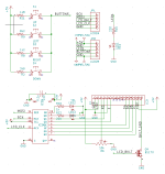
There is an ADC input on the ATMEGA (Pin 23) that reads voltage, when it sees specific voltages it registers the corresponding button press. Each button is supplied +5V through a specific value resistor that sets that button lead to one of the previously mentioned voltages, and there is one pullup resistor (R1 1K), that's it.

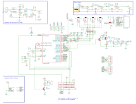
If your buttons don't work I would check that pullup resister on the main board (R1 1K) soldering/continuity and make sure it is actually 1K. Then I would check the four resistors on the button board (R2, 8, 9, 11) and make sure you have the +5V there. The connector between the main board and the button board is potentially the problem. Pin4 on JP8 on the button board is where you should see the resulting voltage from any button press, you can read voltage there as you press each button and see if the various voltages are present. From there you can check continuity from Pin4 JP8 to the same pin on the main board and over to Pin 23 on the ATMEGA. Also make sure there are no shorts to ground (or other voltages) in all of the above places.

Broken button circuit shouldn't be too hard to fix....

On the comments about waterproof buttons, there are so many holes to plug on the HM making a truly waterproof case isn't feasible IMHO. The LCD is a leak, power plug, probes, LAN port are all places that will let water in. The LAN port can be used to allow the entire HM to sit far away from the grill, somewhere it wont get wet, IMHO this is the best way to keep your HM dry..... or you can put it inside some other waterproof case (which is a PITA IMHO)
HeaterMeterLCD.Schematic.png
HeaterMeterPI.Schematic.png
 
On the comments about waterproof buttons, there are so many holes to plug on the HM making a truly waterproof case isn't feasible IMHO. The LCD is a leak, power plug, probes, LAN port are all places that will let water in. The LAN port can be used to allow the entire HM to sit far away from the grill, somewhere it wont get wet, IMHO this is the best way to keep your HM dry..... or you can put it inside some other waterproof case (which is a PITA IMHO)

Agree making waterproof isnt EASY........but some things to make it at least a bit splash resistant.....arent that hard. Took mine apart to inspect.....rust on buttons. Not intended or designed for outside use
 
Dr. Ralph,

Thanks for this detail! I'll get started tracking down the fault. In looking at the circuit, it didn't seem complicated but I just don't have the familiarity with troubleshooting electronics like this. I'll report back.


Back
Top