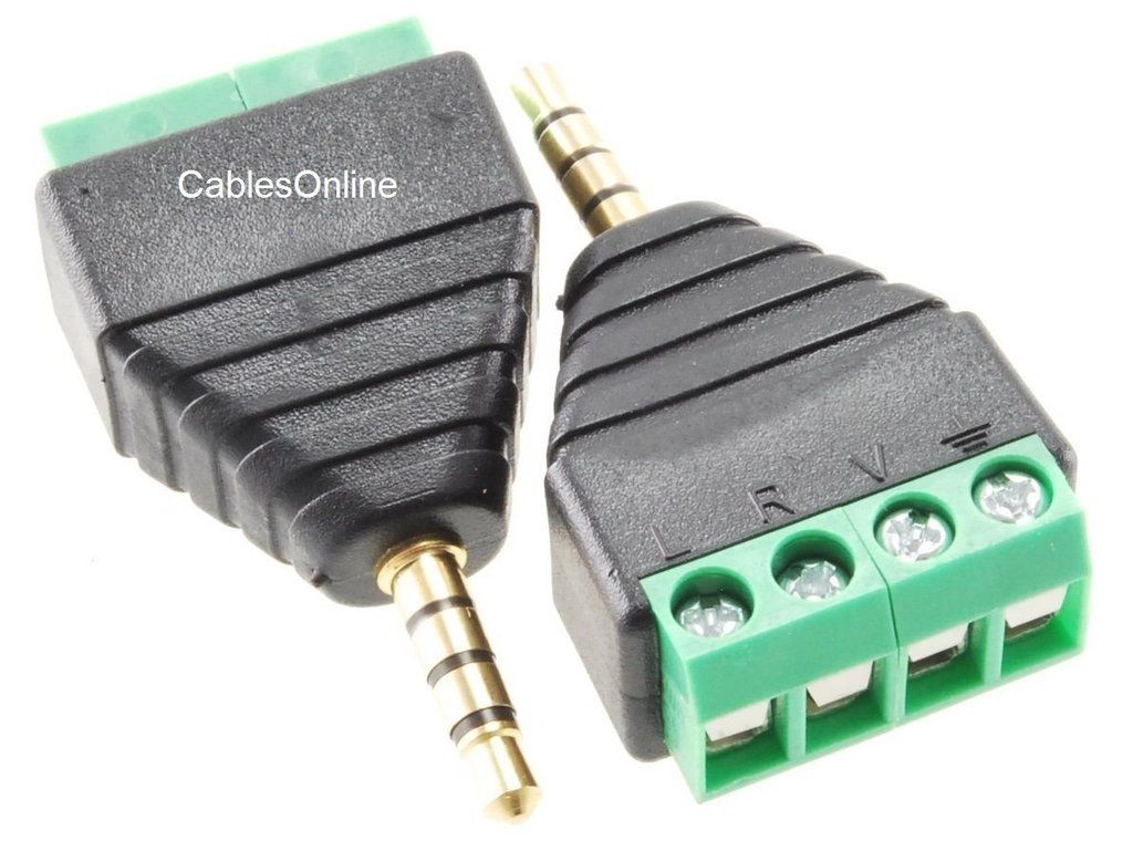
Just a heads up, looks like the wiring diagram here is not entirely correct. Specifically the female TRRS wiring, I ended up needing to do the following (using pin numbers on diagram)
1. Red Servo (5v, RJ45 pin 3, white-green)
2. Red Fan (12v, RJ45 pin 5, white-blue
3. Orange Servo (signal, RJ45 pin 6, green)
4. Black Fan/Brown Server (Gnd, RJ45 pin 4, blue)
I verified the male wiring connection and everything lined up so maybe a difference in the part supplier for the female?
1. Red Servo (5v, RJ45 pin 3, white-green)
2. Red Fan (12v, RJ45 pin 5, white-blue
3. Orange Servo (signal, RJ45 pin 6, green)
4. Black Fan/Brown Server (Gnd, RJ45 pin 4, blue)
I verified the male wiring connection and everything lined up so maybe a difference in the part supplier for the female?
")