You are going about it the wrong way by measuring resistance, the in circuit resistance is going to be different in most cases than what would be measured out of circuit... and the resistance values may fluctuate due to the charge or drain of capacitors in the circuit. If you really want to verify the resistors value you may need to lift one leg to isolate and measure, or check the color code. However, unless you put the wrong resistors in the board I would guess they are all fine, no need to measure. So visually inspect via color codes if you fear you've made a mistake and move on, that would be my suggestion.
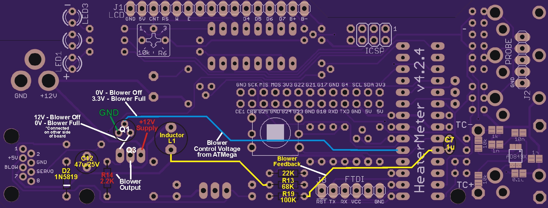
Instead of measuring resistance you want to look at the VOLTAGE in some of the key portions of the circuit to see how the transistors are biased.The blue lead on the diagram above is where the control voltage comes from the ATMega for the blower. When the blower is OFF the voltage there should be 0v, when the blower is at 100% the voltage should be 3.3VDC. As you can see that goes to the top leg of Q1, which in turn controls the MOSFET via connection to the leg closest to the CAT5 jack (the white line). As you can see on the diagram above, when the blower is at 0% those pin(s) on Q1/Q3 should be at 12VDC, when the blower is at 100% those pins should have 0VDC on them. Note the center pin of the MOSFET is the output that drives the blower, and the pin to the right always has 12V on it, so if there is a solder bridge there it can short the blower output to 12VDC so it would remain on.
Take a close look at the MOSFET for solder beads/bridges etc, and measure the voltage in those two spots while the blower is at 0% and 100%, that will tell you more about what is going on. You want to put your meter in DC Volts mode (ranged to measure about 12V if need be on your meter), attach the black lead to any GND and measure with the red lead.