Blower will not turn off, always running from boot


FBerning

New member
Issue:
+ Fan runs 100% even in manual mode, auto mode with temp at 0, or with no probe attached

Details:
+ 4.2.4 build with parts (incl blower) from the Kit (http://heatermeter.myshopify.com/collections/frontpage/products/heatermeter-v4-2-kit)
+ WebUI working correctly
+ Probes working correctly with accurate temp readings
+ Power supply is 12VDC 1.2A

Troubleshooting steps:
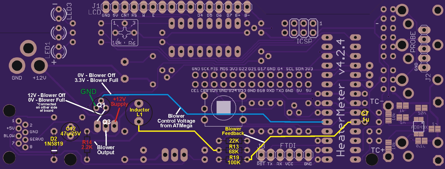
+ Removed Q1 BS170 to see if fan would stop, which it did. Q1 was damaged during removal so replaced with NTE490 (equivalent from Fry's Electronics)
+ Checked 2k2 resistor: Good
+ Checked solder, appears to be good

Feels like next step is to test Q3 FQU11P06TU but Internet videos seem to indicate I need to remove the MOSFET from the PCB before testing. That seems painful since it took my awhile to remove Q1. Any help is much appreciated.


More images: https://goo.gl/photos/5ofLu48LNVobpZk58
 
Last edited:
I had this problem on my recent build; putting the fan in pulse mode fixed it, although to be fair mine did stop at 0, so it may not be the same problem.
 
If putting the fan in pulse mode (kinda) fixed your blower operation then you probably have an issue with the feedback circuit that comes off the blower and connects back to the ATMega (all the stuff to the right if the inductor on the schematic).
OP, make sure you don't have an issue with your wiring of the fan, with the power off check continuity from the wires (in the CAT5 cable) that you are using to power the blower to the pins on the CAT5 jack on the HM, make sure they are connected to ground and the blower pins. Also check continuity between the 2.2K resistor and Q3 (both sides of the resistor). The BS170 could also be an issue here....
 
OP, are you sure you didn't wire in the servo power to fan on accident?

I made this mistake when I first got a HeaterMeter. The fan would vary in output, but would never actually shut off.
 
@Paul: Pulse didn't fix it.

@Ralph: All references from LCD up orientation and unit powered off (see image for numbering references)
Continuity between:
+ BLOW (1) <--> Blue/White Cat5 and Red blower wire = continuity
+ GND (2) <--> Blue Cat5 and Black blower wire = continuity
+ Lower 2k2 resistor pin (4) <--> Upper 2k2 resistor pin (3) = no continuity
+ Upper 2k2 resistor pin (3) <--> Left MOSFET-P Q3 pin (5) = continuity
+ Upper 2k2 resistor pin (3) <--> Right MOSFET-P Q3 pin (6) = no continuity
+ Lower 2k2 resistor pin (4) <--> Right MOSFET-P Q3 pin (6) = continuity

@Nick: Continuity between BLOW and GND. All other pins, no continuity.

Any other ideas?
 
Last edited:
If you pulled Q1 (BS170) and the fan turned off that seems to indicate your blower is wired properly and the blower drive circuit is able to turn the blower on/off, but for some reason it seems to behave opposite of what I would expect. With Q1 absent there should be 0V on the left pin of Q3 which should make the blower spin full speed.

Looking at the solder side of the board with the power connector on the left...

When the HM output is at 0%: (measured from ground)
The top pin of Q1 should show 0VDC and the right pin should show 12VDC (the top pin of Q1 comes from pin 5 of the ATMega, the trace travels under the button so there is a possible source of short to 3.3v there, the right pin connects to Q3 to control it, the left pin should be ground)
(Q1 left to right, Gnd, 0V, 12V)
The left pin of Q3 should show 12VDC and the center pin should show 0VDC (the left pin of Q3 connects to the right pin of Q1, the center pin of Q3 is the output to drive the blower, the right pin of Q3 is the 12V supply)
(Q3 left to right, 12V 0V 12V)
So, when the HM is at 0% Q1 gets zero volts from the ATMega which makes it put out 12VDC, the 12VDC applied to Q3 makes it put out 0V, blower is off...


When the HM output is at 100%:
The top pin of Q1 should show 3.3VDC (VCC) and the right pin should show 0VDC
(Q1 left to right, Gnd, 3.3V, 0V)
The left pin of Q3 should show 0VDC and the center pin should show 12VDC
(Q3 left to right, 0V, 12V, 12V)
So, when the HM is at 100% Q1 gets 3.3v from the ATMega which makes it put out 0VDC, 0VDC applied to Q3 makes it put out 12VDC, blower is on...

With Q1 removed measure the voltage at the top hole while the HM is at 0% and 100% to see if it reads the 0V and 3.3V respectively, that verifies that the proper voltage is getting to Q1 from the ATMega. Since it seems you are getting opposite behavior (blower off when Q1 is removed, which should result in 0V on the left pin of Q3, so the blower should be running full blast rather than being off) I would verify the part number on Q3. It's not impossible you got the wrong part somehow. MOSFETS come in push-pull pairs, perhaps you got the wrong channel somehow...
 
Last edited:
Your Q1 needs soldering. Also you have alot of other questionable solding pads that need to be resoldered and more solder need on some. What I like to do when i have an issue. Is go back over the board with the soldering iron and just make sure all the pads have enogh solder to cover them. Give the board a nice cleaning and check again. Sometimes reinstalling the sd card can help.
 
I am assuming that pic was taken after he removed Q1 for troubleshooting.... With Q1 removed there should be 0V on the left pin of Q3 so the center pin should have 12V and the blower should be blowing full blast. This seems contrary to what you are reporting happening (blower off with Q1 absent, blower full blast with Q1 installed), makes me wonder if you have the wrong channel mosfet in the Q3 position? I would verify the part number on Q3, I tried to zoom in on your pic but can't see the part number on Q3.... but yes, if Q1 isn't soldered in place then it can't apply 12V to the left pin of Q3 and can't turn off the blower. So that leaves the possibility that your original Q1 was damaged somehow (perhaps overheated during installation) and if the new Q1 has not been soldered in place there is no way for it to do it's job and turn off Q3. However, if at this point Q1 is still not soldered in I would pull it out and measure the voltage on the top pin when the HM is at 0% and 100% before you solder it. This allows you to verify that the proper control voltage is getting over to the blower circuit from the ATMega.....

PS I just noticed these seem to be different pics you have up now, and it looks like Q1 is installed backward to me? It should be installed so it matches the shape printed on the board, it looks like the flat side is facing away from Q3 in the pic when it should be facing toward Q3 as indicated by the flat side on the silk screen outline.
 
Last edited:
Yep, it does look backwards. But he said he replaced it with a NTE490 and the pins are not the same as the BS170 they could be just the opposite, knowing NTE.
 
Thanks for the troubleshooting recommendations, especially RT.

I have ordered additional parts, specifically Q1 and Q3. I'm hoping, along with more solder, new parts will do the trick. I should know this weekend.
 
Did you do any of the testing I recommend? Since it appears your Q1 is not soldered in place it should be easy to do.
With Q1 removed measure voltage on the top hole for Q1 when the HM is at 0% and 100%, look for 0V and 3.3v respectively, this confirms the proper control voltage is getting to from the ATMega to Q1. Also measure and record the voltages on all 3 pins of Q3, which should be the same at 0 and 100% with Q1 removed, and report what the fan is doing. This info will be helpful in deciding what to replace. It looked like you soldered the back tab of Q3 to the board, which is OK but totally unnecessary. This will make it harder to remove, so perhaps you want to avoid doing that if it is functioning properly...
 
Last edited:
I am out of town until tomorrow. I intend to follow your troubleshooting steps but will have replacement parts, should they be required. Seriously appreciate all the support. I know I'm close.
 
If you pulled Q1 (BS170) and the fan turned off that seems to indicate your blower is wired properly and the blower drive circuit is able to turn the blower on/off, but for some reason it seems to behave opposite of what I would expect. With Q1 absent there should be 0V on the left pin of Q3 which should make the blower spin full speed.

Looking at the solder side of the board with the power connector on the left...

When the HM output is at 0%: (measured from ground)
The top pin of Q1 should show 0VDC and the right pin should show 12VDC (the top pin of Q1 comes from pin 5 of the ATMega, the trace travels under the button so there is a possible source of short to 3.3v there, the right pin connects to Q3 to control it, the left pin should be ground)
(Q1 left to right, Gnd, 0V, 12V)
RESULT: Gnd, 0V, 15.68V
The left pin of Q3 should show 12VDC and the center pin should show 0VDC (the left pin of Q3 connects to the right pin of Q1, the center pin of Q3 is the output to drive the blower, the right pin of Q3 is the 12V supply)
(Q3 left to right, 12V 0V 12V)
RESULT: 15.68V, .46V, 15.68V
So, when the HM is at 0% Q1 gets zero volts from the ATMega which makes it put out 12VDC, the 12VDC applied to Q3 makes it put out 0V, blower is off...


When the HM output is at 100%:
The top pin of Q1 should show 3.3VDC (VCC) and the right pin should show 0VDC
(Q1 left to right, Gnd, 3.3V, 0V)
RESULT: Gnd, 0V, 15.68V (yes, really no change)
The left pin of Q3 should show 0VDC and the center pin should show 12VDC
(Q3 left to right, 0V, 12V, 12V)
RESULT: 15.68V, .46V, 15.68V (ugh)
So, when the HM is at 100% Q1 gets 3.3v from the ATMega which makes it put out 0VDC, 0VDC applied to Q3 makes it put out 12VDC, blower is on...

With Q1 removed measure the voltage at the top hole while the HM is at 0% and 100% to see if it reads the 0V and 3.3V respectively, that verifies that the proper voltage is getting to Q1 from the ATMega. Since it seems you are getting opposite behavior (blower off when Q1 is removed, which should result in 0V on the left pin of Q3, so the blower should be running full blast rather than being off) I would verify the part number on Q3. It's not impossible you got the wrong part somehow. MOSFETS come in push-pull pairs, perhaps you got the wrong channel somehow...

Do I have a bad Atmega? I have one I can pull from an Arduino board, for testing.
 
Alright, there is some good info....

First off, your PS is running high (15.68V) but that's not a problem really...

Secondly, is Q1 removed during these readings or installed? If Q1 is removed then the top pin (hole) is a dead end trace to the blower pin of the ATMega (pin5), you should be seeing the voltage vary from 0-3.3V when the HM goes from 0-100% on the top hole (and on pin5 of the ATMega). If this is not what you are seeing then you have a problem there. Either the trace is shorted to gnd or something, or the HM config isn't telling the blower to blow, or you have something hosed up with the ATMega. Again, take these measurments with Q1 removed and the blower set to PULSE mode in the config because voltages will float oddly in Voltage mode if the circuit isn't complete and blower attached.

Should be easy to see if there is a short on that trace, but you can also pull the atmega and re-install it with pin5 bent out so it doesnt go in the socket, then measure pin5 directly while the HM is at 0% and 100%. If it still is 0V all the time then the first thing I would do is reflash the ATMega, maybe a fresh flash will fix it. I would also tell you to go over your blower settings in the config carefully, set max and startup max to 100, set blower on above 0%.
 
Last edited:
It works!!!

I think it was all software. I changed to Pulse mode and then followed your directions for blower confit settings. It worked after that. I changed back to Voltage and it still works in Auto and Manual mode. I then soldered Q1 and verified it still works.

I suspect the original Q1 was bad (or destroyed during installation) and then, during my random troubleshooting, I screwed up the blower settings. After installing a new Q1, I still had incorrect blower settings. Whatever the case, it's working now.

Thank you for the support. You are a treasure to the HM community.
 
Hey everyone, I've got the same problem. Blower runs non stop. At 0% there is 9.8v across blow & ground. When the fan is at 100% I get 12v across blow and ground. I don't really want to remove Q1 because I'll break it for sure and never order a replacement. With the solder side up and power on the left I got the following readings at Q3. Fan 0% 12v, 9.8v, 7.8v. Fan 100% 12v, 12v, 0.

Are these readings no good because I have Q1 in still or do they help you guys?

Do you have HMv4.3 or HMv4.2? Below is an image of the HMv4.2 board with some color coding and voltage data attached that may be helpful. If you have the v4.3 board the blower circuit is the same but the component placement is different.

HM_Blower_Notes.jpg


I just took a look at the v4.3 board renderings, I assume you have the HMv4.3 board because the Q1 voltages you report seem to be flipped (Q1 is on the top of the 4.3 board and the bottom of the 4.2 board)

Your voltage measurements show the control voltage Q1 sends to Q3 is only sweeping from 0-7.8V, it needs to go all the way up to 12V to shut off the blower completely...

The first thing I would do is go to the HM Config and set the blower to Pulse mode, this will eliminate the feedback circuit. See if the blower will slow and stop in Pulse mode, that will give you an idea where to focus.

After you test in pulse mode I would measure the voltage on the center pin of Q1, which is the control voltage output from the ATMega, compare to the voltages listed on the image above (should sweep from 0-3.3v). If they are odd you can easily trace the lead over to the pin on the ATMega and measure it there to confirm.

From there you need to suss out where you may have a bad/misplaced component, or bad solder joint, solder bridge etc. Posting closeup pics of the board will allow other forum members to help diagnose the latter...
 
Last edited:


Back
Top