I'm updating this thread to reflect a few observations that I've made regarding the servo dampers. The barrel servo has worked well for me, but in the last few months I have found that the rotary valve design is much easier to print and probably works even better. I will leave the barrel servo information up but am also including the source files and pictures of my rotary designs. There is an offset and in-line version.
Offset rotary valve
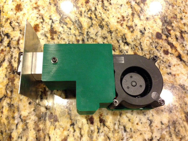
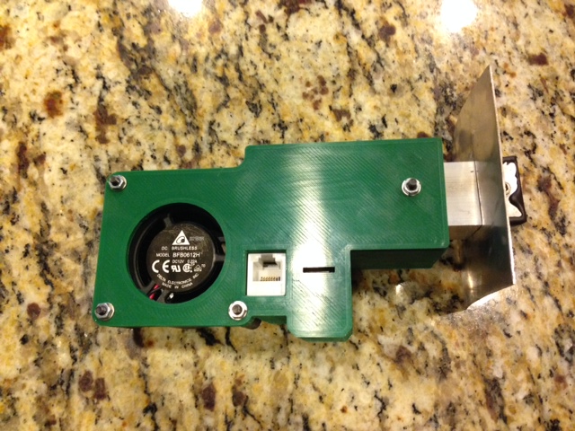
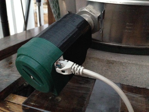
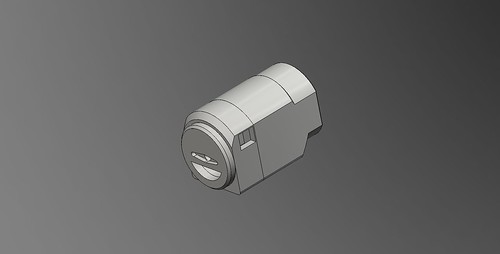
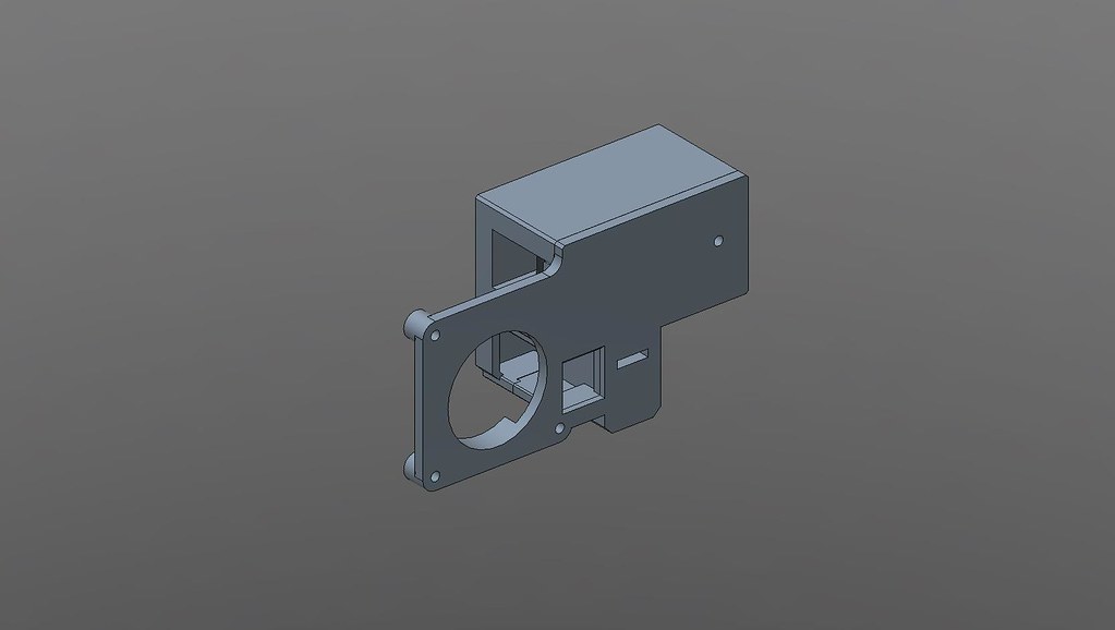
I designed this based on the rotary valve concept and a idea that Bryan had started but I think he abandoned along the way. My goals were to have a physically attached blower with completely separate air ducts and motorized components, a wider opening at the blower inlet, and to make it so that I could mostly shield the electrical parts from the weather since it seems to rain every time I bbq. This is what I got:

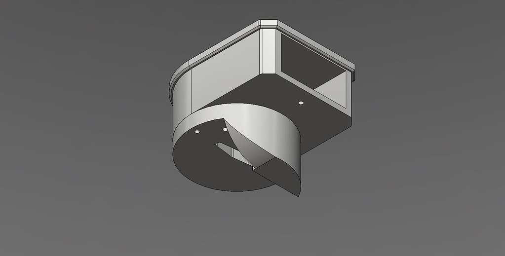
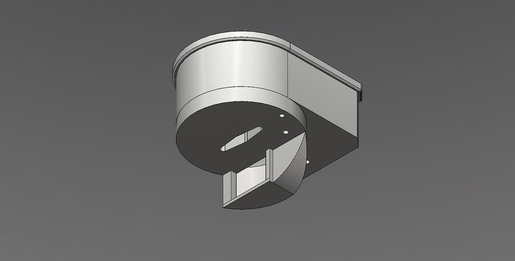
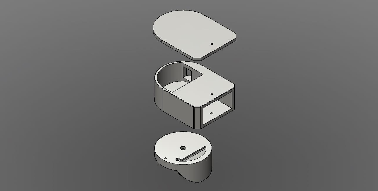
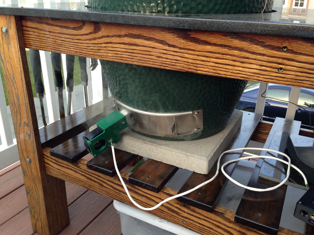
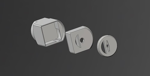
It prints in 3 pieces without any supports. The cover piece pops on and can be secured along with the rest of the unit to the 2" x 1" square tube that attaches to the smoker. The cover doesn't actually play any role in sealing the air ducts, it's just there to keep water out of the electrical/mechanical chamber.
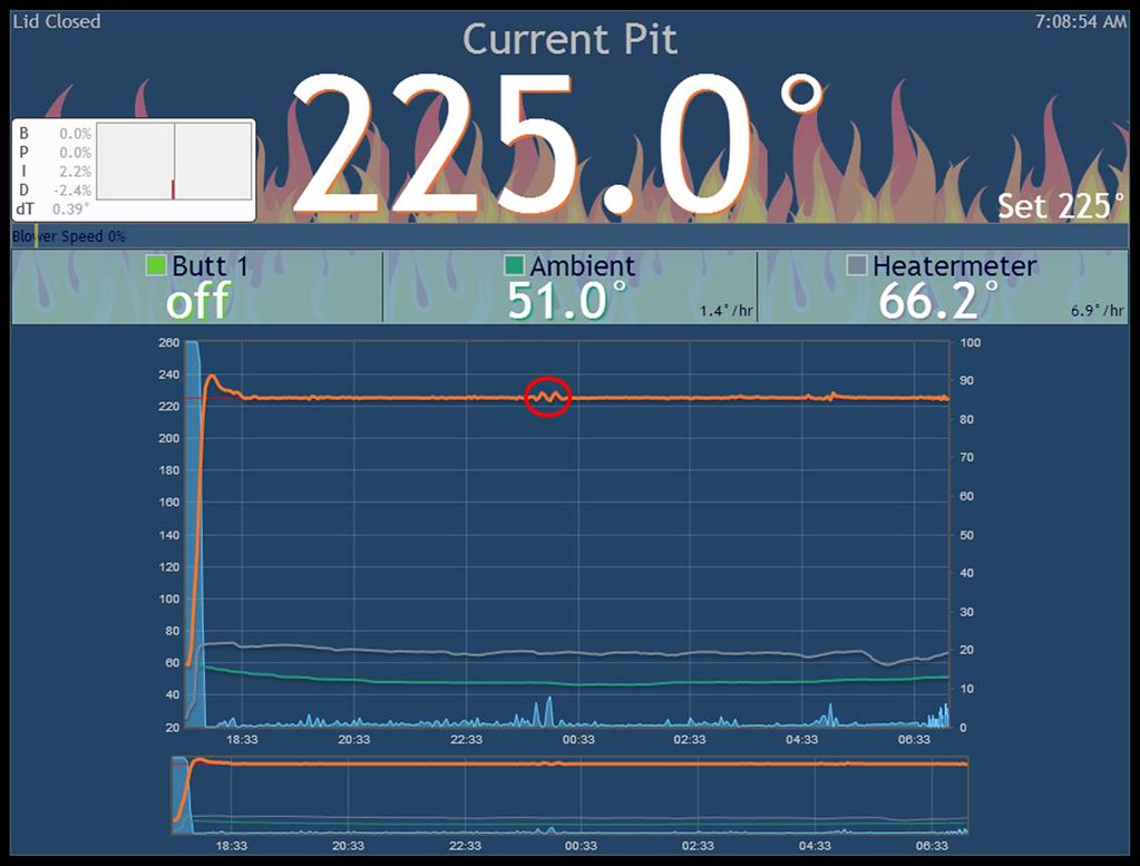
Here is the graph of my torture test. Bear in mind that there is no food on the smoker which could alter the response times.

Large BGE
B: 0
P: 3
I: 0.008
D: 5
min fan: 10%
max fan: 100%
both fan and servo on
Anyone with access to a 3D printer that wants to try it, here are the files. The raw files were created in Inventor fusion and I also put up the corrected .stl files.
The blower is different than the stock blower listed in the BOM. I found a smaller footprint blower on digikey that matched the original blower in static pressure, airflow, and current draw:
http://www.digikey.com/product-search/en?x=0&y=0&lang=en&site=us&KeyWords=603-1370-ND
I couldn't find it's 2-wire version so I just cut off the tach wire.
In-line rotary valve
Here are the files.
Barrel servo
I'm starting a new thread for my new 3d printed barrel servo/fan combo instead of hijacking the 3d print thread. It is designed for the standard blower listed in the heatermeter BOM and the servo's used by D Peart in his original design. A homedepot TECH brand RJ11 jack for 6-conductor wire is incorporated to carry fan and servo control over a single wire. It is designed to mount onto 1" square tubing. All screw holes are designed for M3 hardware.
As of version 2, I started using MG90s servos for better torque and durability. You can find them here, or ebay. They are slightly different in size than the SG90s so I have two different designs. If you don't have any servos yet, I'd go with the MG90s. Version 2 will be the last version to support SG90s.
Version 2
I tweaked the barrel cover so that the barrel and electronics are completely covered and created a conduit for the fan wires to travel to the rj11 jack.
Here is a video demonstrating it's capabilities. It starts with the fan on 100%/servo valve open, then goes to fan off/servo valve closed, then back to fan on 100%/servo valve open, and finally to fan on 100%/servo valve closed.
Barrel damper
Here are the files.
The .stls are already repaired via netfabb. I suggest using the support feature in slic3r for printing the cylinder.
Mount
The mount can be fabricated in the following manner:
Supplies: aluminum sheet (I forget the exact gauge but is should be fairly bendable to conform to the curvature of the smoker), 1" square aluminum tubing (barrel damper) or 1" X 2" aluminum tubing (rotary damper), a 1" chisel, hammer, metal snips, JB weld or high temp silicone, and a drill with 1/8" drill bit.
1. Cut out a 77 mm square (1" square conduit) or a 105 mm X 77 mm rectangle (2" X 1" conduit) from the sheet metal (for large BGE, adjust dimensions for your smoker)
2. Draw an "H" in the middle with dimensions of 1"x 1" (1" square conduit) or 2" X 1" (for 2" X 1" conduit, make the "H" two inches tall)
3. Use chisel to pierce through metal along the borders of the "H"
4. Use hammer to bend back the newly formed tabs at 90 degree angles
5. For the barrel damper, insert a 2" piece of 1" square aluminum tube through the square hole until the edges line up with the end of the tabs. For the rorary damper, insert a 3" piece of 1" X 2" aluminum tube through the square hole until the edges line up with the end of the tabs.
6. Use 1/8" drill bit to drill a single hole through the tabs and metal tube
7. Use an M3 or 1/8" screw to fasten together
8. Place JB weld or high temp silicone along the tabs and edge of the tube that is protruding through the sheet metal to form a nice airtight seal
Offset rotary valve
I designed this based on the rotary valve concept and a idea that Bryan had started but I think he abandoned along the way. My goals were to have a physically attached blower with completely separate air ducts and motorized components, a wider opening at the blower inlet, and to make it so that I could mostly shield the electrical parts from the weather since it seems to rain every time I bbq. This is what I got:
It prints in 3 pieces without any supports. The cover piece pops on and can be secured along with the rest of the unit to the 2" x 1" square tube that attaches to the smoker. The cover doesn't actually play any role in sealing the air ducts, it's just there to keep water out of the electrical/mechanical chamber.
Here is the graph of my torture test. Bear in mind that there is no food on the smoker which could alter the response times.
Large BGE
B: 0
P: 3
I: 0.008
D: 5
min fan: 10%
max fan: 100%
both fan and servo on
Anyone with access to a 3D printer that wants to try it, here are the files. The raw files were created in Inventor fusion and I also put up the corrected .stl files.
The blower is different than the stock blower listed in the BOM. I found a smaller footprint blower on digikey that matched the original blower in static pressure, airflow, and current draw:
http://www.digikey.com/product-search/en?x=0&y=0&lang=en&site=us&KeyWords=603-1370-ND
I couldn't find it's 2-wire version so I just cut off the tach wire.
In-line rotary valve
Here are the files.
Barrel servo
I'm starting a new thread for my new 3d printed barrel servo/fan combo instead of hijacking the 3d print thread. It is designed for the standard blower listed in the heatermeter BOM and the servo's used by D Peart in his original design. A homedepot TECH brand RJ11 jack for 6-conductor wire is incorporated to carry fan and servo control over a single wire. It is designed to mount onto 1" square tubing. All screw holes are designed for M3 hardware.
As of version 2, I started using MG90s servos for better torque and durability. You can find them here, or ebay. They are slightly different in size than the SG90s so I have two different designs. If you don't have any servos yet, I'd go with the MG90s. Version 2 will be the last version to support SG90s.
Version 2
I tweaked the barrel cover so that the barrel and electronics are completely covered and created a conduit for the fan wires to travel to the rj11 jack.
Here is a video demonstrating it's capabilities. It starts with the fan on 100%/servo valve open, then goes to fan off/servo valve closed, then back to fan on 100%/servo valve open, and finally to fan on 100%/servo valve closed.
Barrel damper
Here are the files.
The .stls are already repaired via netfabb. I suggest using the support feature in slic3r for printing the cylinder.
Mount
The mount can be fabricated in the following manner:
Supplies: aluminum sheet (I forget the exact gauge but is should be fairly bendable to conform to the curvature of the smoker), 1" square aluminum tubing (barrel damper) or 1" X 2" aluminum tubing (rotary damper), a 1" chisel, hammer, metal snips, JB weld or high temp silicone, and a drill with 1/8" drill bit.
1. Cut out a 77 mm square (1" square conduit) or a 105 mm X 77 mm rectangle (2" X 1" conduit) from the sheet metal (for large BGE, adjust dimensions for your smoker)
2. Draw an "H" in the middle with dimensions of 1"x 1" (1" square conduit) or 2" X 1" (for 2" X 1" conduit, make the "H" two inches tall)
3. Use chisel to pierce through metal along the borders of the "H"
4. Use hammer to bend back the newly formed tabs at 90 degree angles
5. For the barrel damper, insert a 2" piece of 1" square aluminum tube through the square hole until the edges line up with the end of the tabs. For the rorary damper, insert a 3" piece of 1" X 2" aluminum tube through the square hole until the edges line up with the end of the tabs.
6. Use 1/8" drill bit to drill a single hole through the tabs and metal tube
7. Use an M3 or 1/8" screw to fasten together
8. Place JB weld or high temp silicone along the tabs and edge of the tube that is protruding through the sheet metal to form a nice airtight seal
Last edited: