v4.2.4 - Done broke it..


Tom Steed

TVWBB Member
Hi, I've just built the 4.2.4 and it works fine up to a point. The lcd just displays large blocks, 2 rows during post then one when booted. The wireless works great, all the probes respond. The thermocouple works. The PI works from a 5v usb supply and the whole thing from the 12v. I've checked for shorts, dry joints, bad joints. The trim pot works and the lcd function in luci also works and i can control the backlight. I've either got a duff lcd or i've hosed a component on the pcb. Any ideas which might be the culprit.
Thanks
Tom.
 
I would check the shift register, the smaller chip that looks like the Atmega, and all the connections between that and the LCD and the Atmega. Sometimes you can put to much solder on the lcd connection when you are installing it on to the board, I had a similar problem recently. desolder a bit of the solder on the LCD may help or anything in-between that and the Atmega. Posting a up close picture of the board on the forums to might help with getting it working to.
 
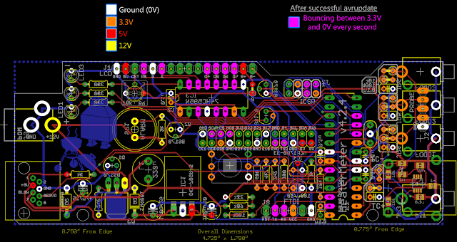
Dang, so close! I'd suggest grabbing multimeter and checking the pins along the LCD to see if those which should be switching on and off are properly switching on and off (fuchsia here)


If all the pins aren't "wiggling" then check the shift register for the same. From there we can tell where the problem lies.

Bryan,

Thanks, here's the metered out..
J2 - 4.7v on USB, 4.98v on 12v
J4 - 3.32v
J6 - Bouncing but only in the 15mv range
J11-14 - Bouncing but only in the 15mv range
J15 - 4.7v, same as J2.

I also metered the 595 and taking that pin 1 is top left then pins 3,7,13 and 14 have a solid 3.32v reading.

I've ordered some more 74HC595N ic's and i'll put a socket on board next time.
 
Well that does sound like the shift register is working and sending data to the LCD. The 15mV is fine because what you're seeing is it switching to 3.3V for a fraction of a second then back to 0V and the multimeter sort of averages it. My pins 11-14 are all usually 3V then bounce down occasionally, although it really depends on what the last byte of data sent is. A blank space (no probes) would be a 0 so that checks out.

If turning the contrast pot doesn't make the magic happen ~0.8V measured at pin 3 of the LCD, then it seems like the LCD itself might be at fault. That would be the first time I've ever seen that in hundreds of HeaterMeters so that seems terribly improbable. I am pretty sure the LCDs are tested before leaving the factory so getting a DOA LCD would mean it's been damaged after the fact. Things are pointing to the LCD but it just seems really really unlikely that that would be the problem unless there's a connection problem between it and the HeaterMeter.
 
Thanks for the update, i'll try the chip first as it's the cheaper option, if there's no change i'll order another lcd. The only way to see the blocks is to turn the trimpot to full or set the contrast in luci to 100%.
 
I remembered i had a spare lcd from the v4 build so i piggy backed it and it works.

So i'll be ordering a new lcd...
 
Welp what do you know, I guess there's a first time for everything. If you can remove the LCD without destroying it, I'd be interested to know if it works in the piggyback fashion. It's just so bizarre, I've never seen a DOA LCD.
 
I ordered another set of parts with 2x lcd's. I'll build another one, just for fun.. i'll try piggy backing the lcd to see what happens.
 
I don't want to hijack this thread but I have a very similar issue. My HM v4.0 worked when I first soldered it but now that I am close to final assembly my screen has went wonky on me. The trim pot is adjusting the backlight so I'm fairly confident the cabling is correct.

I am getting 4.9V on the correct pins but on the ones that should be bouncing around I'm getting a steady ~1.5V. Does this sound like a bad shift register?

9rcMQA2.jpg


UBZmkFv.jpg


My goal is to get this thing assembled today so any and all help is deeply appreciated.
 
Last edited:
The cable seems to be kinda long. Could you test it with a shorter one? The 1.5V could be due to the pins switching back and forth too rapidly for the multimeter to register. Does the shift register get warm? Did you measure it with the display connected? If so try measuring it without the display and see if you get a different result.
 
I just plugged it in and nothing got warm at all. I have touched up all of my solder joints since that seemed to be a recurring theme for issues lately but it still has the same issue.

I disconnected the display and rechecked my voltages and they all dropped to 0V.

I don't have a shorter cable handy but will try to shorten the one I have if I can.
 
Yeah, this isn't supposed to happen. Possibly there is a short or a bad connection somewhere on the power supply rails.
 
For mine, even though I had a 2 line display and not 4, I believe my LCD issues were probably caused by a loose ATmega328 chip. Though I also touched up all solder joints as well.

Dave


Back
Top