The Development Log


Bryan, have you determined if the noise when the blower turns on is due to a dip in the +3VDC that is used for the temp circuits or is it due to noise on the ground from eddy currents, or just interference between circuits? Depending on the source perhaps we could boost up the stability of the 3V supply with bigger caps, or isolate the blower/servo grounds and/or circuitry from the temperature circuits?
 
I am planning on building a 4.1 board this weekend. Other than the barrel jack ground mod, are there any other mods I should make to the board?
 
Bryan, have you determined if the noise when the blower turns on is due to a dip in the +3VDC that is used for the temp circuits or is it due to noise on the ground from eddy currents, or just interference between circuits? Depending on the source perhaps we could boost up the stability of the 3V supply with bigger caps, or isolate the blower/servo grounds and/or circuitry from the temperature circuits?
When I made this new board I separated the two grounds, which is what really helped the v4.1 board. It also runs a ground return path along the bottom edge of the board. I knew I was going to have to do another revision to fix the schematic error too, so while I was waiting I also spent some extra time rerouting a lot of the power traces so the next revision would be even better than this. Unfortunately, this revision is just as bad as v4.1 (without the wire fix).

To isolate the problem I've been going at this board with a razor blade and a soldering iron.
  • Remove the blower output trace and route it out of the way of the analog lines
  • Move blower MOSFET pullup resistor to bottom of board so that one terminal is out of the way of analog
  • Remove 12V input trace and route with wire out of the way
  • Add additional ground wire under 12V trace to provide better current return path
  • Add atmega VCC decoupling cap
  • Add atmega AVCC decoupling cap
  • Cut all analog lines running to probe jacks and thermocouple, removing them from their atmega pins
  • Cut all analog ground lines to the probe section
  • Add 3V3 ceramic cap
  • Add additional 3V3 power circuit, connected directly to AVCC only, decoupled, with 5V wire directly to source
  • Direct thermocouple wiring and 3v3 power
  • Direct analog ground trace (two different ways)


So far the only thing that has made a noticeable difference is putting the AVCC on its own 3V3, which was then degraded when adding 3V3 to the thermocouple. So that's pointing me in the right direction, but not even a 75% solution. I've also experimented in software with using the 1V1 internal reference voltage to isolate if it is a ground problem or an input power problem. In addition, I've been reading every whitepaper about isolating analog circuitry and it makes me wonder how HeaterMeter ever worked at all without all the suggested isolation circuitry.
 
I am planning on building a 4.1 board this weekend. Other than the barrel jack ground mod, are there any other mods I should make to the board?
So far that's all I've got. It makes a lot of difference with removing the lion's share of noise so ET-732 probes don't flicker on and off at low temps and there's not much of a chance of phantom button presses activating Lid Detect Mode. I plan on revisiting it further once I have been able to fully isolate the problem.
 
Bryan, how bad is this problem in real live conditions? I am going to build 14 heatermeters for members of our local Dutch BBQ forum and I have 15 HM4.1 boards already in transit from China to the Netherlands. I would hate to trash them and spend more money on the revised boards, not to mention the extra delay.:( Non of these heatermeters will use thermocouples.

When I look at your drawings I notice that you don't use a 100nF capacitor between pin 20 (AVcc) and pin 22 (AGND). In the reference designs and also in the Arduino schematics a capactior is used between these pins. Also I notice that C3 is connected to pin 21 (AREF) and GND, in the reference designs pin 21 is not connected at all.

Anyway, keep up the good work and I hope you will find an easy fix for the HM4.1 boards.
 
I've used a v4.1 a couple of times without the fix and wouldn't have even known there was a problem if Tom hadn't pointed it out. Adding the white wire fix solved his problem and reduced the noise levels significantly. You can't really see the noise in actual unmodified HeaterMeters unless the ADC is at the edge of its sampling range. ET-732 probes with 10k resistors are bad at room temperature for example. This is because HeaterMeter uses 512 measurements per second per probe to compute the value so the noise is sort of averaged out.

Long story short, I wouldn't worry about it but I'd definitely use ET-72/73 probes and add the white wire fix.

EDIT: Forgot about the rest. Yeah HeaterMeter hasn't had decoupling on AVCC ever and it hasn't been a problem. The AREF capacitor is connected because the datasheet says it "can improve noise immunity". I have added one to AVCC on my test board and it makes no difference. I haven't tried removing the AREF one though, I'll try that this weekend. The datasheet also recommends a 10uH inductor to connect AVCC which we don't have. In other Atmel datasheets they recommend 10uH coupling to the supply in general, and using a ferrite bead with 50ohm impedence @ 20MHz. None of this stuff was on any of my previous boards, which never showed any issues which makes me hopeful that I can get by without it with clever positioning on this board. There's just not enough room to put the proper components in the proper place on any v4 series HeaterMeter board.
 
Last edited:
Hey guys first of all great work on implementing the heatermeter


Been lurking around here for about a month and just finished building a version of the heater meter board. By a version it is based upon Bryan's 4.1 board. I had some concerns about noise and layout on the analog lines on the 4.1 board so I moved some parts and made what I think is a better ( lower noise) on adc inputs version. It has almost a solid ground plane on bottom. I would be glad to hand it back over to the community as it uses all the same parts ( except the power input connector)

I don't have all of the history on all the versions, but i wanted to pro type the analog t couple amp on probe 3 so I removed the rf module and placed it in the board. Probably not a good mechanical fit for the existing cases but it was my first proto. I plan on trying to update design to mount LCD to board and add in some mounting holes for rpi to hm board.

Teddy
 
Just got my first HMv4.1 together tonight. It powered up, flashed and worked great straight out of the gate. It's holding steady with my Thermoworks probes at room temp (about 67 degrees), my 732 probe is dropping off at this temp but that is what I have come to expect from this probe around this temp with my HMv4.0 as well. I jumpered over the first 3 probes and a dedicated probe ground to the CAT5 jack and they all seem to be working the same over the CAT5 through the Roto Damper as when connected directly. I hope to do a test cook tomorrow, initial tests indicate all systems are go...
HMv41.jpg
 
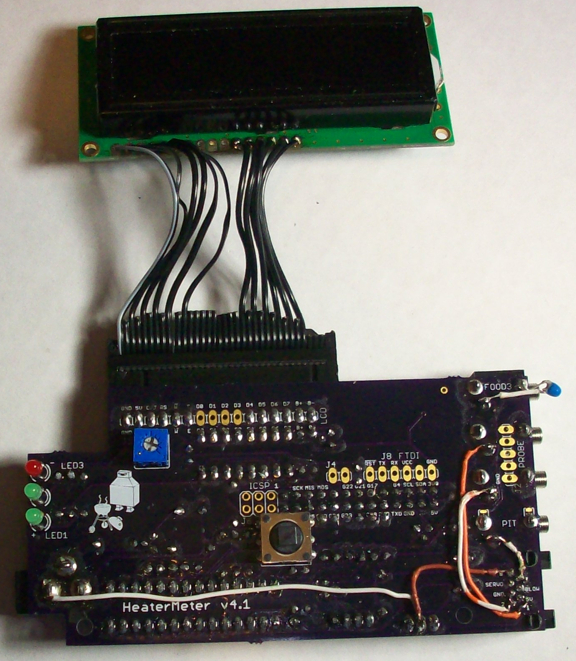
It's nothing special or secret... There are 4 pins on the onboard CAT5 jack on the HMv4.1 that are not use (the outer two on both sides). I just jumpered over a ground to Pin 8, the pit probe to Pin7, and probe 1 & 2 to pins 1 & 2... I did take pictures so here you go...

HMv41Wiring.jpg


The way the jumpers are wired the probes will work through the CAT5 cable, but if you plug a probe directly into the HM the CAT5 cable will be disconnected and the HM will read the probe that is connected directly to the HM instead (for that one probe, so you can mix and match if you want for whatever reason).

You also see Bryans "white wire mod" which is where I pick up the ground for the probes (brown wire).

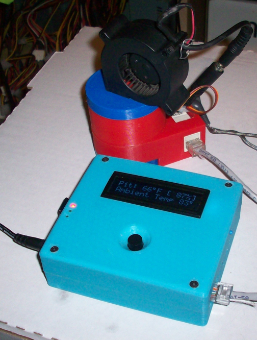
In this picture you can also see what I came up with for the display wiring. Tom made this HMv4.1 case extremely small (and well done!) so there wasn't room for a header and ribbon connector on both ends. I decided to hard wire to one side and have a connector on the other. I used a floppy cable, cut off the end, then soldered it to the display. Since we only use one row of pins we need EVERY OTHER wire in the ribbon, and keep in mind there are a couple extra pins so choose one side and work from there. I chose to put the stripped wire on the ground pin of the display and work from there. On the HMv4.1 board I used two 6 pin right angle headers, one on each end of the display header (cause the center pins are not used, only the six pins on the outer ends are used for the display), you can see I didn't bother to attach wires to the center unused pins on the display. I faced the pins down (toward the rPi), the floppy ribbon connector interferes with the rPi lan port just slightly so it forces the boards to mate slightly "catty wampus" for lack of a better word, but they work fine and still fit into the tight case so all is good... The reason I did this was because I had a case for the 2-line display printed up that I wanted to use for now, but will be printing a case for my larger 4-line display in the future and will be changing over to that, so I didn't want to solder the display directly to the board and have to remove that header later...
 
I was making some steaks on the grill last night so I thought I'd throw the thermocouple out there to see how it does at temperature. The 3V3 analog reference and thermocouple are isolated on their own power supply and direct off-PCB wiring back to ground.

204F - Very noticeable 60Hz hum from the power line here. The thermocouple output has a 16Hz low-pass filter on it which should be reducing this by at least -10dB but there's still 15F of variation peak to peak.
NsoTjRe.png


410F - I don't even know what sort of noise this is. It looks like maybe two out-of-phase sources overlaid on each other. 46F variation peak to peak.
34KFhp8.png


Both of these are with no blower so that's not a potential noise source. Also, strangely enough, touching any metal part of the BBQ seemed to cause some sort of interference despite there not being any sort of electrical connection between it and the HeaterMeter (thermocouple shielding is fiberglass).
 
I was making some steaks on the grill last night so I thought I'd throw the thermocouple out there to see how it does at temperature. The 3V3 analog reference and thermocouple are isolated on their own power supply and direct off-PCB wiring back to ground.
Both of these are with no blower so that's not a potential noise source. Also, strangely enough, touching any metal part of the BBQ seemed to cause some sort of interference despite there not being any sort of electrical connection between it and the HeaterMeter (thermocouple shielding is fiberglass).

Here is an interesting tibit about micro controllers and thermocouples, I'm not sure if you would find it interesting/useful. What kind of wiring do you have to/from the thermocouple? Is it twisted pair to reduce the chance of interference? Is it shielded? I'm a noob and I'm sure you have already tried these things, just trying to do what I can to help.

I'm really excited about this feature for the possibility in using it in high temp cooks like pizza north of 750 degrees F. Due to the nature of this thing, would it be easier to do bring-up/isolation on it using it as a wireless probe?
http://www.mosaic-industries.com/em...rement/thermocouple/thermocouple-noise-filter
 
I've used several different thermocouples from Auber as well as a Chinacheap one I can't say for sure if the wires are twisted in any of them but I'd find it strange if they weren't on at least one. The thermocouple is actually filtered and amped off-board and then there's just a "high voltage" (0V-3V) analog line coming in. I can't tell if the sinusoidal error is coming in from the amp board or being generated on the HeaterMeter board because I haven't hooked up the oscilloscope at higher temperature. I'm focusing more on eliminating the normal noise first then going to work my way towards the thermocouple.

I spent another few hours last night working on that. I've put 50+ hours into trying to drop the noise levels and I'm starting to lose hope that I have the ability to do it. If I don't work it out in the next few days, I'm most likely going to redesign the HeaterMeter board with the output on the left side.
 
Thanks for your efforts Bryan. FWIW, I have relegated my issues with the 732 probed to noise from the PS. If I use wal wart with the hi freq VR I get all sorts of bad readings and drop outs even at high temps. If I use a transformer based PS it functions normally.
 
Bryan, couple questions...
I've been thinking about ways to nail down the noise issue a bit, since power supply noise has been speculated to be a/the problem I was thinking about experimenting running the HM on different power supplies to see if there was a difference. This lead me to thinking, why not try running the HM on a 12V battery briefly to see how much noise that eliminates to get an idea how much of the noise is coming from the PS. Similarly with guitar effects pedals, they usually work silently with a battery but lots of noise/hum gets introduced when you plug them into a wall wart, so perhaps a brief run on a battery is worth a try as a test?
That leads to my second question, how do you get your HM to show that second more detailed graph?... and can anyone make their HM show that or is that special development code you have on your machine?
 
I've run it on a bench power supply which uses a linear regulator and there's still the baseline problem. I haven't tried it at temperature though to see if the waves are there because I figure what's the point if you can't get it clean at room temperature. I'll probably rig up some sort of heater block this weekend just for fun or drag it all over the 3D printer to have a stable heat source.

The noise graphs come from some special development code and rely on code in HeaterMeter and the webui (also the linkmeterd I believe, compared to the last release) to function. If you want to see it too, you need
/usr/lib/lua/luci/lucid/linkmeterd.lua
/usr/lib/lua/luci/view/linkmeter/index.htm
and this firmware on your heatermeter hm-noise-20140214.hex which reports as version 20140117B on the web ui. After you update the files on the Pi you must reboot to refresh the luci cache. They work fine with stock HeaterMeter so there's no need to save the originals and you can switch back and forth just using the AVR update.

By default the Pit probe noise is shown every 5 seconds. You can change which probe it is using the raw set command (bottom of the config page) tp=,X where X is the ADC pin 5=Pit, 4=Food1... 0=Buttons. Note that the comma is significant. Do not leave it out.


Back
Top