Some LCD characters are solid black


Louis P

New member
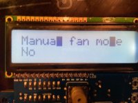
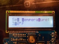
So this happened. LCD was working great on my v4.3, but then I misplaced the Pi Zero W on the header (hello magic smoke), and after that, the LCD starts to show full black characters where there should be an L, l (the lower case of "L"), D, d, and 4. Had this been a parallel connection, I would have found the bad line, but since this is connected by I2C (I think), I'm at a loss.

I have 2 different v4.3 boards and 2 different LCDs boards (for I and a friend). I made a few different swaps and that particular LCD board has this issue with both main boards, and the other LCD board has no issue with either main boards.

Any thoughts as to what the issue might be? The last thing I want to do is de-solder all 16 LCD connections, especially since it's conformally coated. (plus the LCD is expensive)

Thanks!
 
Oof that sucks. I don't have any direction to point you, other than to say that it is a parallel interface. The connections from the chip to the LCD are standard 4-bit Hitachi parallel protocol. The connection from there to the ATmega is a serial shift connection, but if you're capable of debugging a parallel connection then you're good to probe away because that's what it is from the top of the 74HC595N chip to the LCD pins (RS, W, E, D0-D3).
 
Were the LCD characters in question originally rectangular with a vertical bias, and perhaps red in color and intimating a point of ingress or egress?
 
Were the LCD characters in question originally rectangular with a vertical bias, and perhaps red in color and intimating a point of ingress or egress?
Not sure I understand the question. But see below for pictures showing the characters being full black (regardless of position on the LCD). The temp was set at 340.
 

Attachments

  • IMG_3448.jpg
    IMG_3448.jpg
    25.5 KB · Views: 1
  • IMG_3447.jpg
    IMG_3447.jpg
    29.5 KB · Views: 1
Oof that sucks. I don't have any direction to point you, other than to say that it is a parallel interface. The connections from the chip to the LCD are standard 4-bit Hitachi parallel protocol. The connection from there to the ATmega is a serial shift connection, but if you're capable of debugging a parallel connection then you're good to probe away because that's what it is from the top of the 74HC595N chip to the LCD pins (RS, W, E, D0-D3).
Thanks Bryan. Looking at some specs about the Hitachi protocol I see that at least T, t, D, d and 4 are all part of the same b0-b3 bits (0100) and that L and l are part of another (1100). But I can't see any of these bits being bad (nor b4-b7), otherwise other characters would have misprinted as well. And the full black character is 1111 1111. Not sure what's going on here.

1604550104230.png

I don't have access to a scope, so given that a shift register is used might prove impossible to troubleshoot unfortunately. :(
 
I'm not sure how the shift register has anything to do with anything. How would you troubleshoot it if it were just a straight connection to the ATmega without an oscilloscope? The same procedure would apply except the pins in question are physically in a different place (they are on the shift register chip and not the atmega chip). If you can describe how you'd troubleshoot it, I can probably help you translate that to the HeaterMeter hardware layout, because it is literally the standard parallel LCD interface. You can even use the ShiftRegLCD library in the HeaterMeter code repository to directly set all the pins high or low with ShiftRegLCDSPI::write(0xff) or ShiftRegLCDSPI::write(0x00) in a test app.


Back
Top