Peter F
TVWBB Fan
Should be fixed now! http://www.mouser.com/ProjectManager/ProjectDetail.aspx?AccessID=27647396C3
Any chance of their being a solder mask file for stencils?
Chuck
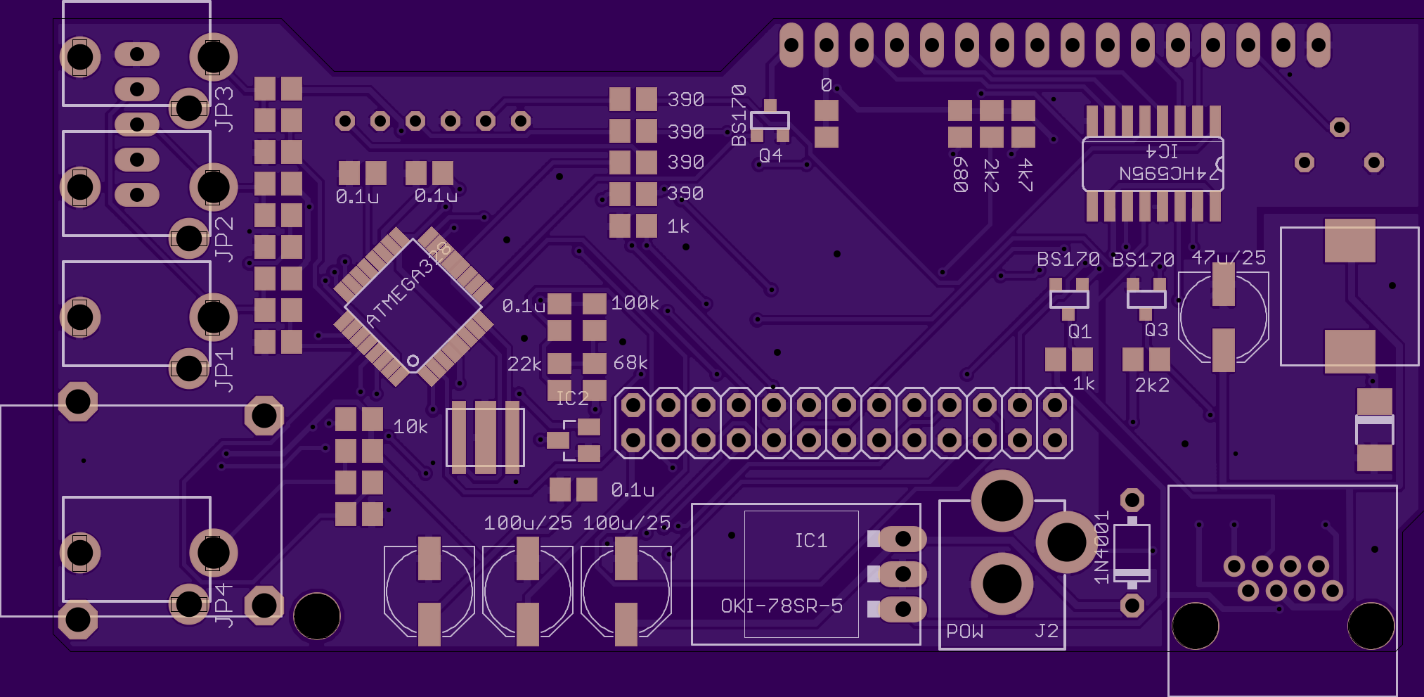
Looks good but you haven't fixed the stupid f*ckup that I've made.
The 0.1uF capacitor just below IC2 should be much closer to IC4, at this position it does nothing! That's what you get when you let the software do all the work.
Hmm, I didn't realize that was an issue. That'll be a bit harder to move. My OSH Park order already went to the fab so no fixing it for this order at least. You been seeing issues on the shift register with that cap so far away?
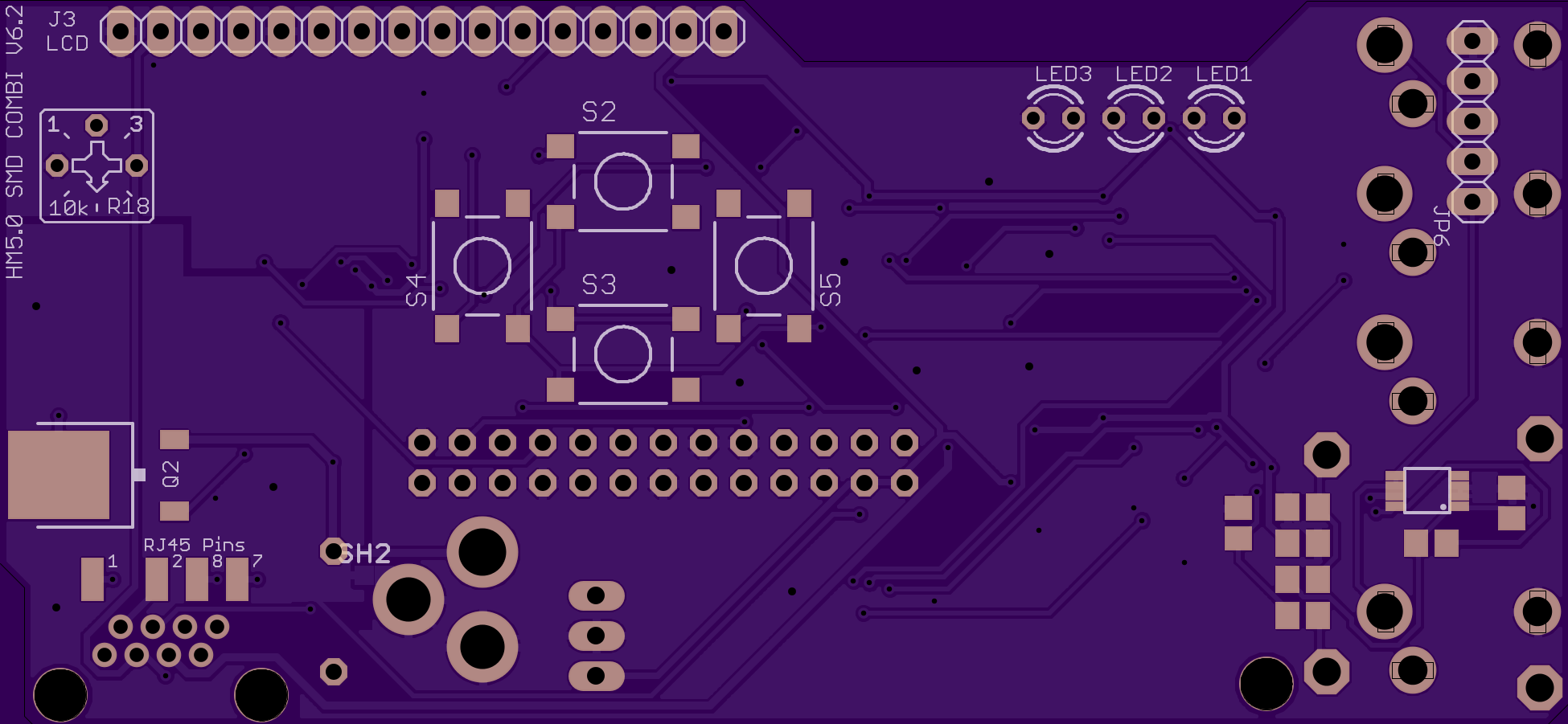
I made a few small updates to the v6.1 design:
OSH Park project: https://oshpark.com/shared_projects/6VXPWWjp
- Switched to tented vias
- Broke out the remaining 4 RJ45 pins to solder pads
Eagle files: https://www.dropbox.com/s/h53mtvkdkjf6k93/HM50SMD_C_V6.2.zip?dl=0
With the regular HeaterMeter board, the size of all the connectors dictates the size of the board and the overall device. You need one side just for all the probes, then the RPi connector is massive (although technically you don't need all the pins), and finally there's the width needed by the LCD. You can save space by moving the connectors to the same side as the LCD starts, but then they run into the Pi's connectors. To get around this you can flip the whole thing 180 degrees but it isn't going to save you even 10mm. Believe me, I've flipped flopped stacked and laid out this board 100 different ways in mockups and the Pi always gets in the way!Have we thought about going with a 4-layer board?
The CHIP is a little better because it is like 2/3 the size of a Pi and doesn't have a bunch of giant connectors on it.


