You are using an out of date browser. It may not display this or other websites correctly.
You should upgrade or use an alternative browser.
You should upgrade or use an alternative browser.
Runaway temps? Cheap fix/long story....
- Thread starter RalphTrimble
- Start date
Steve_M
TVWBB Guru
Lovin this thread. I don't even have my HM built yet but I love the ingenuity of the folks here.
My own thought / mod on this would be to see if you could replace the ping pong ball with the same type of valve you're using in the servo setup. The fan pressure could open the valve and gravity would close it when the air pressure is removed.
My own thought / mod on this would be to see if you could replace the ping pong ball with the same type of valve you're using in the servo setup. The fan pressure could open the valve and gravity would close it when the air pressure is removed.
Bob Ivey
TVWBB Emerald Member
Lovin this thread. I don't even have my HM built yet but I love the ingenuity of the folks here.
My own thought / mod on this would be to see if you could replace the ping pong ball with the same type of valve you're using in the servo setup. The fan pressure could open the valve and gravity would close it when the air pressure is removed.
That is a good thought, but the simplicity of the ping pong ball is brilliant. Also, the only moving part is the ping pong ball and there is much less to fail. Just my two cents worth.
Steve_M
TVWBB Guru
I agree the ping pong ball is brilliantly simple. The only moving part in my proposed mod would be the valve as well, though I suppose there's a greater chance of getting stuck in one position. The nice thing with the internal valve is that unlike the ping pong ball, it won't restrict the air flow when it's activated.
RalphTrimble
TVWBB Diamond Member
Lovin this thread. I don't even have my HM built yet but I love the ingenuity of the folks here.
My own thought / mod on this would be to see if you could replace the ping pong ball with the same type of valve you're using in the servo setup. The fan pressure could open the valve and gravity would close it when the air pressure is removed.
Nope, ping pong ball works way better, gravity and air flow is not gonna close that damper but it does a great job with the ping pong ball. I initially had plans to design a flap valve and print it with my 3D printer, like a trap door that hinges from one side (rather than from the middle like the servo damper), I think gravity would work to close a flap door. However, I still think the ping pong ball makes a better valve, cause it can seat down any which way and will close off well, and there are no moving parts connected to the ping pong ball the create friction and make it hang up like a flap valve would have... Also, the ability to weight the ping pong ball is crucial, a flap might be too light and a little convection flow might open it up a tad and defeat the purpose.
Last edited:
RalphTrimble
TVWBB Diamond Member
I agree the ping pong ball is brilliantly simple. The only moving part in my proposed mod would be the valve as well, though I suppose there's a greater chance of getting stuck in one position. The nice thing with the internal valve is that unlike the ping pong ball, it won't restrict the air flow when it's activated.
Build one and see, the ping pong ball does not restrict the air flow, there is plenty of room inside the PVC tube for air to go around the ball.... A flap valve will float on the air and offer the same sort of resistance as the ball, if it didn't there would be no force to close the valve.
The short valve can be built for less than $3 dollars in about 10 minutes, give it a try and see. You only need so much air flow to stoke the grill and this valve allows way more than you need. In the next few days I will do a pizza cook which will prove the ball does not hamper the air flow, if it can stoke the grill to over 600 degrees that's enough flow I would say...
Last edited:
RalphTrimble
TVWBB Diamond Member
Ralph, if possible, can you post the dimensions of the new and improved (shorter) version. Also, the piece you modified so the ball would pass air, could you specify the dimensions of the cuts. TIA
Bob, I'm afraid that ship has sailed, cause the valve is assembled and it can be a real PITA to get it back apart, I already took some skin off of one finger pulling it apart once to swap in the weighted ball. The rings on the short valve are roughly 1/2" wide, the channels are cut deep enough to just leave about 1/4" of ring left to seat in the PVC. A longer valve works just as well as a short one, so it's up to you how short (or long) you want to make it. If you don't want to saw anything just jam the whole coupler in the PVC, if you want it as short as possible just make thinner rings....
The good news is this isn't rocket science. To make the small valve you just need one 1" coupler. Start off by making sure the coupler fits into the 1/5" PVC tube (some of the couplers would fit on one side but were a bit imperfect on the other side so they didn't fit or were real tight, you only need one half so pick the side that works best. You could sand the side that don't fit but why bother, you don't need it). Then make sure the ping pong ball sits well on the top of the side that fits in the PVC, if there is any imperfection in the top lip of the coupler just sand it off lightly so the ball sits on it nicely (I didn't have to do this but you might, depending on the coupler) Make sure you insert the factory edge of the coupler into the PVC for the ball to sit on, an imperfect cut from a saw will give you an imperfect seal....
Now that you have chosen the side of the coupler you will use insert it into the PVC about 1/2", doesnt have to go far, just enough to sit in there snug. It's only job is to mate tightly with the PVC and the ping pong ball. Now take a saw and cut the coupler, I used the PVC to guide my cut. Now you have the bottom ring ready.
Now take the coupler and cut another ring for the top. The only thing this ring has to do is be a bushing between the threaded part and the PVC, about a 1/2" or so is good. You also have to cut the threaded adapter down so there is just about the same amount of mating surface for the ring to go over. Now push the ring on the threaded adapter and you are almost done.
The slots for air to flow around the ball are not precise, I just pushed the unit from above (threaded part with coupler ring on it) against my bench grinder to cut those channels, so they are as wide as a bench grinder wheel for reference. You could use any manual tools you have, saws, files, whatever, but the bench grinder made light work of it. The only thing you need to watch here is that you leave enough on the ring to grab and seal in the PVC tube.
Now just push the threaded part with the ring (and channel cut in it) into the PVC. Throw the ball in there, blow from the bottom and air should flow around that ball with no resistance when its pushed against the top. If there seems to be any resistance to air flow make those channels deeper/bigger.
At this point you can see where the ball sits when it is pegged against the top, now mark the place to cut the PVC to length by leaving enough room for the bottom ring to go in there and about 1/2" for the ball to travel. The ball doesn't have to move far, but it can, again, not rocket science.....
Now just put the ball in and push in the bottom ring and you're done! When you blow from the bottom air should flow with no resistance, when you blow from the top it should seal off pretty good and barely allow any air to flow. If the PVC ends up a bit long you can always cut it shorter.
I didn't write a step by step originally because I think the description actually makes it more complicated than it is. Really, its just two rings in a tube with a ball between it, the length of the tube and rings has no effect on the function, long or short it will work the same...
Perhaps a real world reference would be helpful for putting things in perspective...
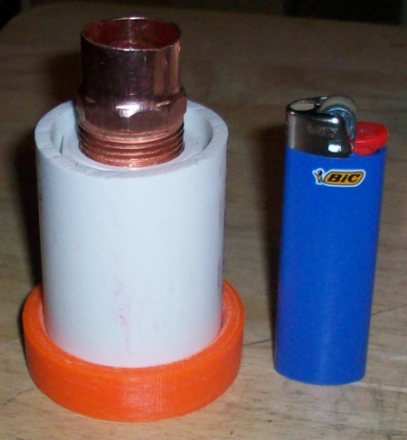
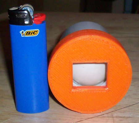
The orange ring on the bottom is the fan adapter I made on my 3D printer. You don't really need it, you can attach your fan any way you see fit. A piece of metal or plastic with a (square) hole cut into it that fits the fan, then secure it to the valve with silicone, would be an easy way to go.
As for weighting the ball, I did the first test of the short valve with a non-weighted ping pong ball. I lit the grill and set the target temp to a super low 185 degrees. (This FauxMado always wanted to shoot up over 300 degrees in the past no matter what I did, so landing on 185 degrees would be a miracle) The temp maxed out at 189 degrees and then slowly went down to 185. This was pretty incredible, but since the non weighted ball still required the fan to blow a fair amount before it lifted I decided to weight the ball a bit to make it have a little better seal. I figure a small fire burning at ~190 has a small draft, if the set point were higher there would be more draft and that might make the valve leak a bit. So I added some salt to the ball (and taped it closed) but I only put about half the amount of salt as I used when testing the prototype valve. (1/2 tsp maybe?) I expected the ball to float much easier (with only half the salt inside), but in reality it didnt start to float until the fan was blowing at over 20%, which is not far from the 30% setting with the heavier ball. The good news about that is you can put a fair amount of weight in the ball and it will still function, which will help it stay closed for larger and very well sealed grills.
I ran a test with the weighted ball and min fan speed set to 20%, the temp was fairly solid but I noticed a slight saw tooth pattern on the pit temp developing which I hadn't seen on the first test. The fan graph showed the fan on a moderate amount for a while then it jumped WAY up, following the spike in fan speed the saw tooth pattern appeared on the pit temp. I figured the ball wasn't opening up air flow enough at 20% so the HM was fooled into thinking it was stoking the fire when it wasn't, when the pit temp didnt respond the HM ramped up the fan at which time the ball jumped up and massive air started to flow causing the saw tooth overshoot. So I set the min fan speed back to 30% and the saw tooth went away, the pit temp was rock solid again.
This experiment showed that the weight of the ball is not very critical, within reason. It can work without any weight added, but will seal better with a little extra weight to it. Whether weighted or not you should set the min fan speed to about 30% so when the HM tells the fan to put out air the air is actually delivered to the pit, otherwise the HM can not properly calculate the required flow to achieve the desired pit temp.
Last edited:
Bryan Mayland
TVWBB Hall of Fame
As someone who has build a bunch of different flaps, that's key right there. I've built flaps out of light cardboard that were too light to close when the fan was off. I've built flaps out of a strip of metal that restricted the airflow too much. I've built spring-loaded flaps which always seemed to wedge themselves into the tunnel and get stuck. I must have tried a couple of dozen materials and configurations. That's why I'm so excited about this, it is the perfect combination of materials and application.Also, the ability to weight the ping pong ball is crucial, a flap might be too light and a little convection flow might open it up a tad and defeat the purpose.
RalphTrimble
TVWBB Diamond Member
Trust me Bryan, I spent HOURS pondering how I could design a valve that would do the job which could be printed in my 3D printer. I designed and printed two myself, both failed miserably. One of the two failed attempts was a float type of valve very similar to this, but I used a hollow cylinder instead of a ball (kinda hard to print a perfect ball). The cylinder always got wedged and wouldnt reliably return to the home/closed position. That is when I came up with the idea for the ball, but had no source for a ball (I was thinking smaller than ping pong at the time). The thing about the ball is it has to be very smooth so it will seal when it lands, and it has to be very light so forced air can make it float. Guess what, ping pong ball is exactly that! Just one night watching the lotto drawing is enough to paint that picture! The ease of drilling and filling the ball to make it the perfect weight is the final key to making the valve work, for any grill....
Bottom line, the ping pong valve functions perfectly, and is about as cheap and easy to make as I can imagine. Trust me, while pondering this for a few weeks I never thought I would get the job done so simply....
Bottom line, the ping pong valve functions perfectly, and is about as cheap and easy to make as I can imagine. Trust me, while pondering this for a few weeks I never thought I would get the job done so simply....
Last edited:
Bob Ivey
TVWBB Emerald Member
Ralph, I like what you have done. Your description is very helpful. I picked up a pack of ping pong balls this morning on my way back from a service call. $6.00 for six. Maybe my grand daughter will want to play with them? Sold a large job this week (praise God), so won't have a lot of time for a few weeks but I will make this ASAP and will report back on how well it works with my WSM 22. I like your orange piece for the fan. You said you sealed the hole in the ball with tape. I am wondering if the tape will fail over time from heat and the air flow. Also, if the ball should rotate and be in line with the position where the ball seal the tube, would this be enough to create a problem? I was thinking of using something like fingernail polish to seal the hole. When it dries it could be sanded smooth. From the pictures it looks like the ping pong valve (or PPV), should be as vertical as possible?
Just a few thoughts. I am looking forward to trying this on the WSM. They don't seal as well as your fauxmodo but it should work.
Just a few thoughts. I am looking forward to trying this on the WSM. They don't seal as well as your fauxmodo but it should work.
RalphTrimble
TVWBB Diamond Member
Bob, I sealed the hole in the ping pong ball with some of the aluminum tape I had sitting around which I use to tape off the vents in my regular smoker. I got it from Home Depot in the section where you find supplies for chimneys and ducts etc. The tape itself is aluminum, it has a pretty good adhesive on the back and has a backing that you must peel before you stick. So it works out pretty well, I cut a small circle of aluminum tape with scissors and then peel and stick. You can smooth the aluminum out really well with your thumb nail and get all the wrinkles out and it seems like it will stick indefinitely I would think... It is thin enough and smooth enough that it could land on the tape and the valve would still work, however, I think the ball with salt in the bottom should land in a pretty similar position each time if the travel in the tube is short. My shorty valve only has a tiny bit of travel in it (you can push the top and/or bottom rings in after you assemble it to adjust the travel of the ball) so I'm not too worried about any of the issues you raise with the ball.... I actually think finger nail polish would make for a more irregular surface than the aluminum tape...
My valve sits about 15 degrees or so off vertical and works fine at that angle, I haven't really tested it at steeper angles... but you are right, the closer to vertical the better theoretically... but it can and does work well leaning a bit... I would say give it a try at the natural angle it has connecting to your grill, if the angle is too great and it's not closing off for you then perhaps bend the copper tube a bit to correct the angle. One good thing about copper that it is fairly soft and flexible...
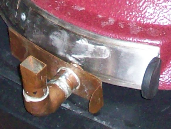
The fan adaptor I made with the 3D printer is nice, but you can do just as well with a hammer, vise and copper. Take a look at the fan adapter I made here as an example, see how I hammered the 3/4" copper tube square? It fits right into the stock HM fan perfectly. You could make something like that and connect it to the valve the same way I connect the copper on the top of the valve. It would be a little longer than my 3D printed version, but it's still a cheap and effective way to attach the fan. Or if you need super low profile, take a piece of plastic or metal, trace the pvc tube onto it, then map out an opening for the HM fan in the center of that. Now cut out the square and circle and use silicone to attach it to the bottom of your ping pong valve....
Below is an example of how to make 3/4" copper fit into the HM fan to use as in your ping pong valve or other fan adapter....
My valve sits about 15 degrees or so off vertical and works fine at that angle, I haven't really tested it at steeper angles... but you are right, the closer to vertical the better theoretically... but it can and does work well leaning a bit... I would say give it a try at the natural angle it has connecting to your grill, if the angle is too great and it's not closing off for you then perhaps bend the copper tube a bit to correct the angle. One good thing about copper that it is fairly soft and flexible...
The fan adaptor I made with the 3D printer is nice, but you can do just as well with a hammer, vise and copper. Take a look at the fan adapter I made here as an example, see how I hammered the 3/4" copper tube square? It fits right into the stock HM fan perfectly. You could make something like that and connect it to the valve the same way I connect the copper on the top of the valve. It would be a little longer than my 3D printed version, but it's still a cheap and effective way to attach the fan. Or if you need super low profile, take a piece of plastic or metal, trace the pvc tube onto it, then map out an opening for the HM fan in the center of that. Now cut out the square and circle and use silicone to attach it to the bottom of your ping pong valve....
Below is an example of how to make 3/4" copper fit into the HM fan to use as in your ping pong valve or other fan adapter....
Last edited:
RalphTrimble
TVWBB Diamond Member
Glue is a good idea as long as you get the right amount of glue, 'cause there would be no lightening up after it goes in there. But on second thought it may not be a good idea 'cause if the hole is left open the ball could land with the hole on the seal edge and make the valve leak. (I don't see how you could seal a hole off perfectly smooth with any glue). Then again, a tiny leak would likely be insignificant in the valves function....
I still think there is no problem with using salt inside with tape on the hole, I would be willing to bet the aluminum tape will seal the ball off indefinitely and not present any of the potential problems that have been raised...
I still think there is no problem with using salt inside with tape on the hole, I would be willing to bet the aluminum tape will seal the ball off indefinitely and not present any of the potential problems that have been raised...
RalphTrimble
TVWBB Diamond Member
Hey Bob, did you say you have a WSM? I don't own one, the closest thing I have is my Char-Broil H2O smoker, which I think is fairly similar?
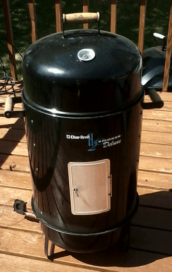
With this smoker I have absolutely no need for a valve on my HM fan adapter, and I would think the situation would be about the same for the WSM? The smoker pictured above is single walled and not particularly well sealed, so it leaks heat like crazy and therefore I have never had problems with runaway temperatures on this smoker. In fact, the HM with the blower tube wide open is able to control the temp in this smoker with much more precision than in my FauxMado. I can hit any temp I want, as low as I want, it is rock solid without overshoot and it will rise or fall and settle on the temp super fast. Basically whatever the HM tells it to do it does PRONTO... It does burn through the coals though....
I would suggest you close off all your vents on the WSM and let the HM be it's only source of air and I think that should work fine without having a valve on the fan adapter??? The only time you need to have the valve on the adapter is if you are getting runway temperatures in your pit.....
Bob Ivey
TVWBB Emerald Member
Ralph, my idea for using this device on my WSM is that I have already done the no ex mod and this thing is reasonably airtight. Not Like your fauxmodo but somewhat. I have found that I have to use painters tape to cut down on the draft from time to time when the fan is not running.. Also when I am shutting down the cooker I have to tape off the fan so I can extinguish the coals.
RalphTrimble
TVWBB Diamond Member
Bob, OK, if you need to tape off the opening to reduce the draft then the ping pong valve will help. If you connect the ping pong valve to the grill via copper like I have shown you may want to buy a copper cap as well. After rain hit my HM (it survived) I am quicker to pull it off the grill, if you pull the ping pong valve the tube is wide open for draft and your coals will burn up, so I put a copper cap on my tube when I remove the HM and the fire goes right out...
Dave Casazza
TVWBB Fan
Anyone run into the issue of having the ping-pong ball be too big? Apparently there are two sizes of ping pong balls, 38mm and a newer 40mm dia. standard. I have the 40mm, and there isn't much clearance for airflow in the 1.5" PVC pipe.
RalphTrimble
TVWBB Diamond Member
Hmm, well, I found the ping pong balls here among some stuff in the basement, they fit nicely into the pvc and the valve developed from that. I never really measured one.... but I do have a spare and it does measure 38mm.
Funny you would mention this today, cause last night I was cleaning out my ash pan and I guess some coal pieces got down into my servo damper and when it (tried to) close it jammed and broke the flap. Since I was ready to cook I needed a valve so I pulled out the handy ping pong valve and used it, I must say it did a supurb job, the temps on the pit were rock solid!
This is a pic of my graph from last night, this is the first one with the recent update that will restore/resume the graph after a power failure, you can see on the graph the brief moment where there is no data because the rPi was rebooting...
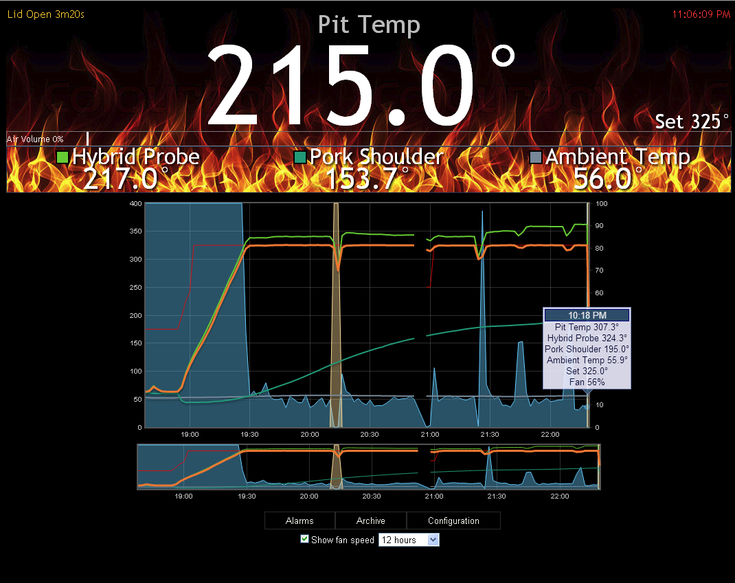
BTW I rebooted the rPi to clear the alarm, which I had set to Text and Email me when the Pork Shoulder hit 160 degrees, then lower the pit temp to 250 degrees. WORKED PERFECTLY, though I decided to finish the shoulder up at 325 degrees cause I wanted it done faster, it was really good....
Funny you would mention this today, cause last night I was cleaning out my ash pan and I guess some coal pieces got down into my servo damper and when it (tried to) close it jammed and broke the flap. Since I was ready to cook I needed a valve so I pulled out the handy ping pong valve and used it, I must say it did a supurb job, the temps on the pit were rock solid!
This is a pic of my graph from last night, this is the first one with the recent update that will restore/resume the graph after a power failure, you can see on the graph the brief moment where there is no data because the rPi was rebooting...
BTW I rebooted the rPi to clear the alarm, which I had set to Text and Email me when the Pork Shoulder hit 160 degrees, then lower the pit temp to 250 degrees. WORKED PERFECTLY, though I decided to finish the shoulder up at 325 degrees cause I wanted it done faster, it was really good....