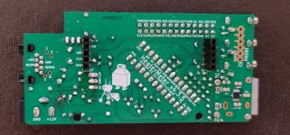
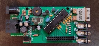
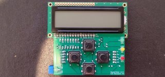
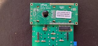
I have a weird situation going on. So I just finished soldering up my HM 4.3, got the software flashed to my Raspberry Pi Zero W, and plug it all in and... I got the issue where I only get one line of black blocks to display and nothing else. It appeared that there was some issue with the ATMEGA not being flashed properly. I reset everything and tried again, wiped and reformatted the SD card to be sure there was no lingering formatting issue, but still the same problem.
After that I just assumed I had missed a solder, so I reflowed all of the solder and visually verified and checked the components to make sure I didn't make any orientation mistakes or swapped resistors. I had no noticeable problems, but then when I plugged in the HM with the RP attached, the RP heated up and broke. Yikes!
After this I ordered a new raspberry pi, and I started checking all the voltages on the board while waiting for the new Pi to arrive. While I was going through checking, the board threw a bunch of gibberish characters on the screen, then fired up and started apparently functioning. Showing pit temperatures and responding to the probes being plugged in and all the buttons appeared to function as well. I thought maybe I had mistakenly shorted something? Maybe that cause it to boot? Not really sure, I unplugged it and plugged it back in, and now I'm back to just the single row of blocks. For all of the voltages, they all appear correct except for LE1 on the Atmega. It is supposed to be 3.3V but shows basically 0V.
Once I get my Raspberry Pi (and I ordered a new SD card just to be sure that it wasn't some kind of older SD card issue) I was planning to get it all hooked up, and try powering it through the 5V connector on the Raspberry Pi. I wasn't really able to troubleshoot the raspberry pi before because I burned it up, so I'll make sure to check the display on HDMI first for errors there.
Is there any reasonable way to figure out what is going on with this thing? It feels like it is really close, especially since I got it all up and apparently working one time.
Thanks!


