Hi All,
I recently completed a HM 4.3 kit build that my wife got me for Christmas 2017 (an indication of my available free time) Unfortunately I'm unable to get the HM to do pretty much anything at all. I've combed through the forums at length and have tried a few things, but without any success. Here's what I have, the symptoms and what I've tried:
HeaterMeter kit for a 4.3 build with a thermocouple option
Raspberry Pi Model 3B 1GB revision 2
v14 of the HM Firmware
I've assembled and connected all the components and loaded the firmware.
I can boot the device and connect via ethernet or wireless connections
The HM shows up in the devices page
I can log in via root to change configuration in the web interface
However I have these issues
- The linkmeter tab provides the error reported by others in the forum
- I've tried updating the firmware through the interface as well as the command line and AVRUpated. In both cases I receive the AVR Fuses error reported by others and cannot proceed further.
- I've confirmed the ATMEGA chip is installed correctly
- I've reheated all the solder joints and cleaned up some that weren't fully filled.
- I've cleaned the boards with denatured alcohol the best I could.
- I've confirmed the LCD adjustment setting
After each of these steps the results were the same:
- The HM registers on the devices page
- I can log in to the web interface and update settings via wired or wireless connection
- Other than the the LCD showing black boxes while adjusting to confirm the correct setting there are no other signs of life from the HM; no LED lights at any time.
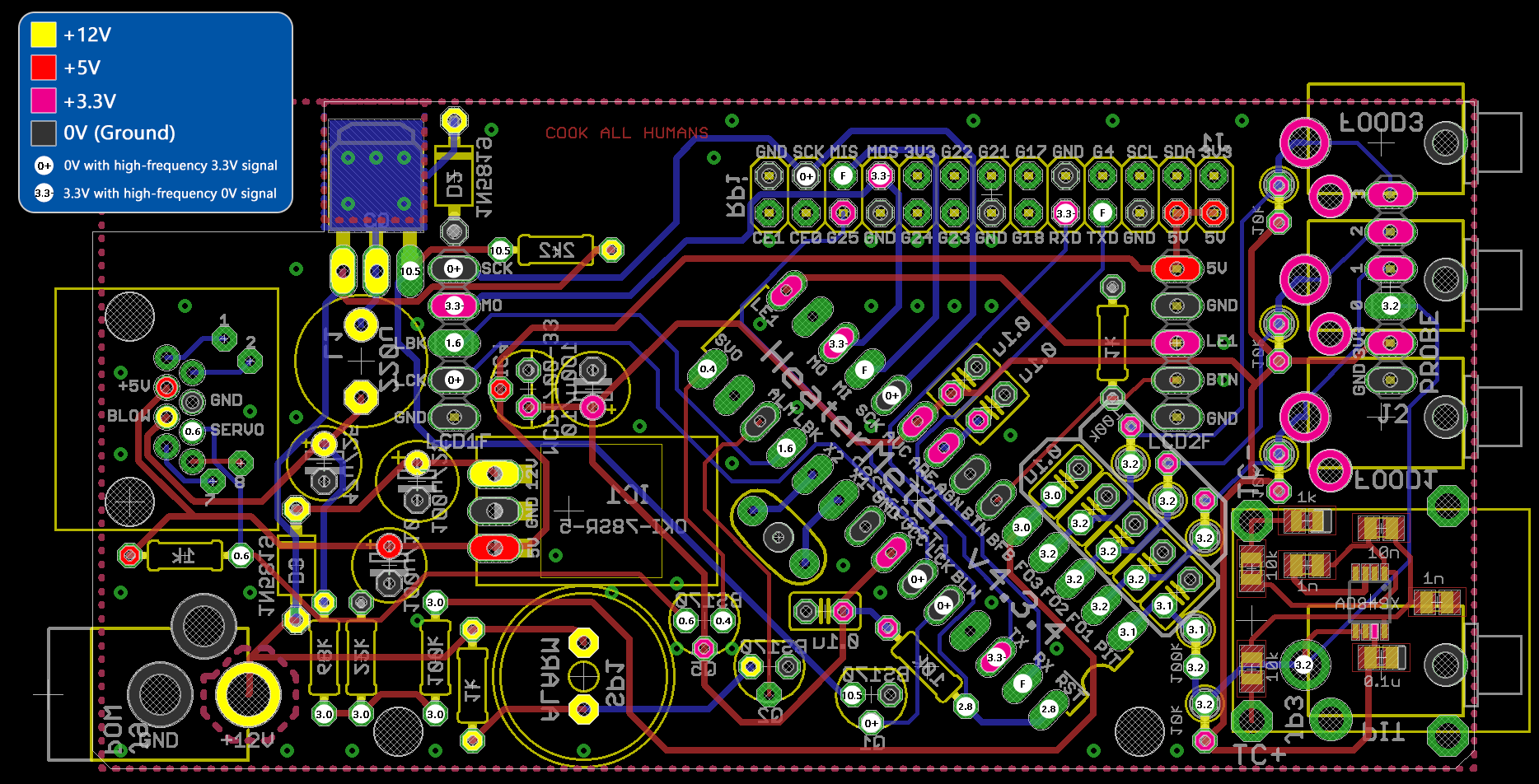
At this point I don't know where to go next. I know I need to test continuity and voltages, but I'm not sure where to start. I have a multimeter, but the use of it on circuit boards is far from my weakest strong point. I did manage to confirm the ground connections, 5v (4.9x) supply to the button board and 12v out of the power supply connector, but that's about it. I'm not sure about the 3.3v points or what the items highlighted in green are meant to represent in the diagrams on the basic troubleshooting link.
I think that's about it. Any suggestions from anyone would be more than appreciated. Thanks!
I recently completed a HM 4.3 kit build that my wife got me for Christmas 2017 (an indication of my available free time)
Unfortunately I'm unable to get the HM to do pretty much anything at all. I've combed through the forums at length and have tried a few things, but without any success. Here's what I have, the symptoms and what I've tried:HeaterMeter kit for a 4.3 build with a thermocouple option
Raspberry Pi Model 3B 1GB revision 2
v14 of the HM Firmware
I've assembled and connected all the components and loaded the firmware.
I can boot the device and connect via ethernet or wireless connections
The HM shows up in the devices page
I can log in via root to change configuration in the web interface
However I have these issues
- The linkmeter tab provides the error reported by others in the forum
HeaterMeter serial communication can not be established. Configuration requires bidirectional serial operation. Possible causes of failure:
No HeaterMeter board attached
No HeaterMeter (AVR) firmware installed. See AVR Firmware
Incorrect baud rate in /etc/config/lucid
Hardware malfunction
- I've tried updating the firmware through the interface as well as the command line and AVRUpated. In both cases I receive the AVR Fuses error reported by others and cannot proceed further.
- I've confirmed the ATMEGA chip is installed correctly
- I've reheated all the solder joints and cleaned up some that weren't fully filled.
- I've cleaned the boards with denatured alcohol the best I could.
- I've confirmed the LCD adjustment setting
After each of these steps the results were the same:
- The HM registers on the devices page
- I can log in to the web interface and update settings via wired or wireless connection
- Other than the the LCD showing black boxes while adjusting to confirm the correct setting there are no other signs of life from the HM; no LED lights at any time.
At this point I don't know where to go next. I know I need to test continuity and voltages, but I'm not sure where to start. I have a multimeter, but the use of it on circuit boards is far from my weakest strong point. I did manage to confirm the ground connections, 5v (4.9x) supply to the button board and 12v out of the power supply connector, but that's about it. I'm not sure about the 3.3v points or what the items highlighted in green are meant to represent in the diagrams on the basic troubleshooting link.
I think that's about it. Any suggestions from anyone would be more than appreciated. Thanks!