New build - thermocouple circuit help needed


Douglas George

New member
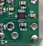
Hello everyone, I'm new here but recently bought a few of the last 4.3.6 boards because I like projects like this and have been wanting to have more control when smoking on my kamado. I built my first board and am having a problem with the thermocouple circuitry. Originally, when I switched it to thermocouple from thermistor it would just read "Off" on the web interface, but I believe I had the .1u and the 1n caps shorted together that are located just below the thermocouple amp. Once I removed and resoldered those, I did get a reading. However, it started at 800+ degrees and slowly dropped and is now hovering around 94 degrees. It took quite a while to drop this much. It sounds like the same problem that was reported (but never solved) here.

I've reflowed solder to everything on the TC circuit, but it has not changed anything. I've put a paperclip in place of the TC and it reads about the same, around 100 degrees and slowly rises, presumably because of my body temperature while holding the paperclip? One thing that I noticed is if I blow on the TC circuitry, it immediately will say "no pit probe" and then a second or 2 later will show a reading again but it will be back up in the 400 - 500 degree range and then work its way back down.

Does anyone have any suggestions or know if a solution ever determined for the problem I linked above? I do have another full set of components with the exception of the TC connector and LCD display, but I was hoping to build a backup Heatermeter and not be short more components.

A few other notes;

  • The thermistor ports all seem to be working properly / reading properly.
  • I used the ATMEGA328-PU (non- "P") instead of the ATMEGA328P-PU
  • I used the AD8497ARMZ instead of the AD8495
Thanks in advance for any help!

Doug
Im not sure if the AD8497 will work with the Heatermeter as it has a cold junction is 25°C-100°C. This means it would not work correctly unless the ambient temperature was 77°F
 
I did find AD8495 on Ebay on a breakout board pretty cheap, couple weeks ago. I bought one, and recieved it a few days ago. Will need to desolder it and solder it onto the HM.
 
Hi John, thanks for the feedback. I should have looked at the datasheet when I ordered the AD8497. I just used the "compare" feature on Mouser to compare it with the AD8495 and they looked very similar. I think I found the board you mentioned on ebay and just placed an order.

On another note, I hit the legs of the AD8497 with the soldering iron 1 more time (this is the 3rd time) and the temp reading is now down to 80 degrees F. Also, when I blow on the TC circuitry, it doesn't say no probe connected anymore. It does raise the temperature to about 105 degrees but then quickly settles back down around 80 degrees. I'm still not convinced that this is normal behavior when blowing on the circuit. I may try to play around with boiling water and setting the probe's offset to see what if its close while I wait for the 8495.

On another note, on the 4.3.6 board, can you confirm that the 0.1u and 1n caps that are located directly below the AD8495 should be 0.1u on top (closest to the AD8495) and the 1n below the 0.1u?

Thanks for all of your help.
Doug
 
If you have the board in front of you and the thermocouple circuit is on the right.

1n is to the left and right of the AD chip.

10n is on top
.,1n is on the bottom
 
Hi John,

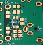
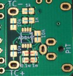
I think I have a different version of the board, but when I took a picture to show you what I have, I had an epiphany. I put these 2 caps in the wrong direction. The board is very clear, I was just going about it all wrong. If you look at the red lines, this is how I mounted the capacitors. I now see that they go vertically (the blue lines) and the markings on the board are actually quite clear.

So, as I was typing this I went ahead and reoriented the caps to match the blue lines and there wasn't much change. turned on the board (by the way, I'm only using the 5V from the Pi. I haven't connected 12v yet, ever). The board initially said no pit probe, but then started out in the 800+ degree range and is slowly working its way down. I will recheck the soldering on these 2 caps tonight when I get some free time but can you confirm the blue lines in the picture are the correct orientation?

Thanks,
Doug

TCcircuit.jpg
 
Oh, I didnt even know the boards were changed. I use a custom board from the 4.3 version to work with my Adapter board.

Anyways, .1u would be on the left and the 1n on the right, just like your blue lines


Back
Top