LinkMeter v2 Homebrew BBQ Controller - Part 1


Status
Not open for further replies.
Originally posted by D Peart:
Have you thought about using 1/8 watt resistors instead of the 1/4 watt ones? They quite a bit smaller and would give you some board space back. All the 10k pull up resistors could easily be 1/8 rated.
I did consider it, but I thought that the 1/4W were generally easier to find at Radio Shack. Now that I look though, it seems they carry both. The board isn't too packed as it is now, the new SPI design I was able to autoroute with no vias and nothing looking janky in my second attempt. I've been keeping it in mind though. The raspberry pi board is actually a little larger in footprint than the V3.1 LinkMeter board so I was thinking that maybe there'd be room to put the probe and fan jacks on the board. However, the barrel jack will have to be populated so that will take some room up too.

Something also tells me getting my hands on a Raspberry Pi is going to be difficult considering they're only making 10,000 in the first run for the whole world. What I'm really afraid of is that once you've got Linux running and the overhead of the video framebuffer and whatnot, that you end up with like 10MB of RAM free and we're right back to running out of memory again. That's like my worst nightmare right there.
 
Originally posted by Bryan Mayland:
...
I've pushed up a new LinkMeter OpenWrt snapshot to my web site. This includes:
-- SHADOWPASSWORDS fix that allows you to set your password through the web interface
-- Adds explicit cache control for static HTTP items which really speeds up page loads in the Chrome browser
-- Fixes the ordering of the Network / LinkMeter tabs so they no longer flip back and forth
...

Thanks Brian!...took a week off to wait on a replacement WRT54G (and play with a new TF201, it should make an excellent LM controller!
icon_biggrin.gif
)... Hopefully the serial's not dead on this one
 
Originally posted by Joe Loyd:
Thanks Brian!...took a week off to wait on a replacement WRT54G (and play with a new TF201, it should make an excellent LM controller!
icon_biggrin.gif
)... Hopefully the serial's not dead on this one
Oh man the Transformer Prime is so sweet. I can't believe the amazing amount of power it has in such a small package. Also, Ice Cream Sandwich! Funny I was just reading the ICS Android design guidelines before I came here. I also saw that ASUS was going to do a Tegra 3 7" tablet soon, which may be right up my alley.

EDIT: Oh I meant to ask you about your router. Was the first one a WRT54GL or what model did you have?
 
Originally posted by Ryan Evans:
Is this a possible wifi shield? wifi shield on ebay
Not really, it appears to be a UART-based model which means it takes serial commands instead of SPI. It probably shares the same limitation that other UART-based designed have, which is that you can't be a server, only a client. I'd look more into it but all their links are either dead or "you don't have rights to download this file".
 
Originally posted by D Peart:
(Regarding V3.2 board) Thanks, I'll take a look.
Did you DorkBot/BatchPCB a V3.2 board? I just put in an order to hopefully get in on today's panel for one of the SPI-register LinkMeter boards. I don't need all 3 obviously, but if it works do you want one? I'd be happy to send you one for free if you'd like one, in thanks for all the help you've been in this thread and debugging stuff.
 
...
Oh man the Transformer Prime is so sweet. I can't believe the amazing amount of power it has in such a small package. Also, Ice Cream Sandwich! Funny I was just reading the ICS Android design guidelines before I came here. I also saw that ASUS was going to do a Tegra 3 7" tablet soon, which may be right up my alley.

EDIT: Oh I meant to ask you about your router. Was the first one a WRT54GL or what model did you have?

Yeah love the Prime, very cool piece of hardware...

The first one (with the fried serial) is a WRGT54G v2.2. I got another one (v4) that the serial seems to be working, I get an echo at least. However, when I hook up the LM, I don't see anything on the port. Not sure where to go from here (other than to start pulling components!)...
 
I was going to suggest changing the baud too but loading programs from the Arduino IDE works right, or are you flashing the whole chip using the ISP?
 
Bryan,
That would be great. I've been thinking of making another one for my parents and that would work out great.

dave

Originally posted by Bryan Mayland:
<BLOCKQUOTE class="ip-ubbcode-quote"><div class="ip-ubbcode-quote-title">quote:</div><div class="ip-ubbcode-quote-content">Originally posted by D Peart:
(Regarding V3.2 board) Thanks, I'll take a look.
Did you DorkBot/BatchPCB a V3.2 board? I just put in an order to hopefully get in on today's panel for one of the SPI-register LinkMeter boards. I don't need all 3 obviously, but if it works do you want one? I'd be happy to send you one for free if you'd like one, in thanks for all the help you've been in this thread and debugging stuff. </div></BLOCKQUOTE>
 
Originally posted by D Peart:
That would be great. I've been thinking of making another one for my parents and that would work out great.
I don't think the last Dorkbot panel went out, so it may be 15 days before I get the boards back. Just email me your address to bmayland theemailsymbol leoninedev.com

I pushed a new build today with the configuration backend I've spent way too much time designing the rewriting. This means... new configuration page! I've just realized that it isn't exactly obvious you click the update url link to commit the changes. Requires HeaterMeter version 201201180
lmconf-20120118.png
 
Cleaned it up a little bit with some style and added the ability to paste whole A,B,C coefficients into any one coefficient box. Also added two click coefficient preset setting.

lmconf-20120119.png
 
Originally posted by Bryan Mayland:
Cleaned it up a little bit with some style and added the ability to paste whole A,B,C coefficients into any one coefficient box. Also added two click coefficient preset setting.

Love it!

I never did resolve the problems I was having with flashing the Atmega through my USBTinyISP and ICSP headers. Tonight, I tried to flash it with a hex file through the web interface for the first time and I got the same error:

Stopping LinkMeter OK
avrdude: stk500_getsync(): not in sync: resp=0x00
avrdude: stk500_disable(): protocol error, expect=0x14, resp=0x24

avrdude done. Thank you.

Failed attempt 0
avrdude: stk500_getsync(): not in sync: resp=0x00
avrdude: stk500_disable(): protocol error, expect=0x14, resp=0x24

avrdude done. Thank you.

Failed attempt 1
Starting LinkMeter OK
Current HeaterMeter version is nil poll

I did follow the instructions on flashing the hex for the first time with the reset button through ssh...same error. Has anyone else had this problem? I would like to resolve this because I just migrated my heatermeter from an external enclosure into my WRT54GL and I don't want to have to open it and pull the chip every time it needs to be updated.

Bryan, are all of your v3.2 boards you ordered spoken for?
 
Dave,

I've had this happen off and on. When I've been modifying the code this can happen when the HM is busy and doesn't respond to the LM.

Most times I can get around this by just retrying the flash, or restarting the HM and flashing again.

Did your HM turn off when you tried to flash? I've noticed that if it doesn't properly shutdown I get this as well.

dave

Originally posted by Dave S (GeoDave):
<BLOCKQUOTE class="ip-ubbcode-quote"><div class="ip-ubbcode-quote-title">quote:</div><div class="ip-ubbcode-quote-content">Originally posted by Bryan Mayland:
Cleaned it up a little bit with some style and added the ability to paste whole A,B,C coefficients into any one coefficient box. Also added two click coefficient preset setting.

Love it!

I never did resolve the problems I was having with flashing the Atmega through my USBTinyISP and ICSP headers. Tonight, I tried to flash it with a hex file through the web interface for the first time and I got the same error:

Stopping LinkMeter OK
avrdude: stk500_getsync(): not in sync: resp=0x00
avrdude: stk500_disable(): protocol error, expect=0x14, resp=0x24

avrdude done. Thank you.

Failed attempt 0
avrdude: stk500_getsync(): not in sync: resp=0x00
avrdude: stk500_disable(): protocol error, expect=0x14, resp=0x24

avrdude done. Thank you.

Failed attempt 1
Starting LinkMeter OK
Current HeaterMeter version is nil poll

I did follow the instructions on flashing the hex for the first time with the reset button through ssh...same error. Has anyone else had this problem? I would like to resolve this because I just migrated my heatermeter from an external enclosure into my WRT54GL and I don't want to have to open it and pull the chip every time it needs to be updated.

Bryan, are all of your v3.2 boards you ordered spoken for? </div></BLOCKQUOTE>
 
Originally posted by Dave S (GeoDave):
I never did resolve the problems I was having with flashing the Atmega through my USBTinyISP and ICSP headers. Tonight, I tried to flash it with a hex file through the web interface for the first time and I got the same error:
How did you end up being able to flash the HeaterMeter onto it? Pulling the ATmega chip out and putting it in something else?

What's unusual is that where it says "expect=0x14, resp=0x24", avrdude is expecting Optiboot to spit out the STK_INSYNC response but it got a '$'. $ happens to be the first character HeaterMeter spits out when it boots (apart from a newline depending on version).

Do you have Optiboot 4.4 on that ATmega? That's the one that comes with Arduino-1.0. Also I seem to remember something about your pins reading 3.3V on the multimeter, is that correct? Which pins were those and did you ever resolve that?

EDIT: Regarding the V3.2 boards, I may have 1 but they are experimental so I'm not sure if they're going to work or what so we'll see. Also the Dorkbot guy said he is running behind and didn't get the last panel out and their site is currently SOPA blacked out so let's see how that works out.
 
Originally posted by D Peart:
Did your HM turn off when you tried to flash? I've noticed that if it doesn't properly shutdown I get this as well.

I assume it turns off when I hit the reset...not really sure how to tell.

I have tried to reset procedure about 100 times with pretty much the same result. The LED blinks twice then there is a couple second delay then then the LED blinks twice again. If I press the reset button after the first LED blink I can sometimes get it to show me the version number of the Heatermeter but I still get the error.

Originally posted by Bryan Mayland
How did you end up being able to flash the HeaterMeter onto it? Pulling the ATmega chip out and putting it in something else?

Yes, I pull the chip every time. I flash the sketch using Arduino 1.0 on the duemilanove.

Originally posted by Bryan Mayland
What's unusual is that where it says "expect=0x14, resp=0x24", avrdude is expecting Optiboot to spit out the STK_INSYNC response but it got a '$'. $ happens to be the first character HeaterMeter spits out when it boots (apart from a newline depending on version).

Any ideas on what could cause this? I am sure I am somehow causing this.

Originally posted by Bryan Mayland
Do you have Optiboot 4.4 on that ATmega? That's the one that comes with Arduino-1.0. Also I seem to remember something about your pins reading 3.3V on the multimeter, is that correct? Which pins were those and did you ever resolve that?

Yes, I am currently running the 4.4 bootloader. I did reflashed it using my USBTinyISP to make sure I had the right one.

I did have some issues with the buttons not working correctly with the 1/4 watt resistors. I also had an issue with the voltage on another routers serial port. If you recall I had damaged the serial port on one router and that is the reason I was getting weird voltages.

So some good news -
I was able to get the ICSP header on the v3.1 to work with my USBTinyISP. I had to remove the power jumper from the USBTinyISP and provide power through the heatermeter board instead of the USBTinyISP. I guess this doesn't really matter though because it seems like you need to have the bootloader on the ATmega to upload the hex file through ttys1. I read that the main purpose of the bootloader is to allow code to be uploaded to the atmega through the SPI.

and

I got my new smoker in the mail today and I am working on putting the system back together. Fedex decided not to deliver mail for the last 3 days because of the snow here in Seattle. I had to go pick the smoker up myself. I guess their drivers decided not to come to work. Wonder why they couldn't show up when I got my good ole USPS government mail everyday this week.
 
Originally posted by Dave S (GeoDave):
I assume it turns off when I hit the reset...not really sure how to tell.
When you press and releast the rest button the LCD backlight should turn off for about a second. Then there should be one blink, the LCD backlight will come on, then another blink (these three happen really quickly but in this order).

When you're doing the reset procedure while SSH/telnetted into the router, are you pressing and holding the reset button, press enter on the `avrupdate` command, wait for it to say "Stopping LinkMeter OK", then releasing the reset button?

The reason you're seeing "expect=0x14, resp=0x24" is because Optiboot isn't recognizing avrdude and it is just booting right to HeaterMeter.

Two things to try:
1) type `echo -e \\n/reboot > /dev/ttyS1` (enter) you should see the HeaterMeter reset (backlight off/on, LED blinks)

2) Try adding verbose to the avrupdate:
2a) `vi /usr/sbin/avrupdate`
2b) Scroll down to the avrdude line and insert "-v -v -v -v" between avrdude and -pm238p (press i to enter insert mode, enter your text, hit escape to leave insert mode)
2c) type ZZ (shift-z shift-z) you should leave vi and be back at the shell prompt
2d) Try the hold-down-reset running avrupdate again and see what you get
 
Originally posted by Bryan Mayland:
When you press and releast the rest button the LCD backlight should turn off for about a second. Then there should be one blink, the LCD backlight will come on, then another blink (these three happen really quickly but in this order).

It does this when I do the hold reset>execute avrupdate>release reset after "Stopping LinkMeter OK".

When you're doing the reset procedure while SSH/telnetted into the router, are you pressing and holding the reset button, press enter on the `avrupdate` command, wait for it to say "Stopping LinkMeter OK", then releasing the reset button?
Yes.

Two things to try:
1) type `echo -e \\n/reboot > /dev/ttyS1` (enter) you should see the HeaterMeter reset (backlight off/on, LED blinks)

Yes, it also does this.

2) Try adding verbose to the avrupdate:
2a) `vi /usr/sbin/avrupdate`
2b) Scroll down to the avrdude line and insert "-v -v -v -v" between avrdude and -pm238p (press i to enter insert mode, enter your text, hit escape to leave insert mode)
2c) type ZZ (shift-z shift-z) you should leave vi and be back at the shell prompt
2d) Try the hold-down-reset running avrupdate again and see what you get

I did this a bunch of times and this is the output:


Stopping LinkMeter OK

avrdude: Version 5.8, compiled on Jan 5 2012 at 12:06:07
Copyright (c) 2000-2005 Brian Dean, http://www.bdmicro.com/
Copyright (c) 2007-2009 Joerg Wunsch

System wide configuration file is "/etc/avrdude.conf"
User configuration file is "/root/.avrduderc"
User configuration file does not exist or is not a regular file, skipping

Using Port : /dev/ttyS1
Using Programmer : arduino
avrdude: Send: 0 [30] [20]
avrdude: Recv: . [00]
avrdude: stk500_getsync(): not in sync: resp=0x00
avrdude: Send: Q [51] [20]
avrdude: Recv: $ [24]
avrdude: stk500_disable(): protocol error, expect=0x14, resp=0x24

avrdude done. Thank you.

Failed attempt 0

avrdude: Version 5.8, compiled on Jan 5 2012 at 12:06:07
Copyright (c) 2000-2005 Brian Dean, http://www.bdmicro.com/
Copyright (c) 2007-2009 Joerg Wunsch

System wide configuration file is "/etc/avrdude.conf"
User configuration file is "/root/.avrduderc"
User configuration file does not exist or is not a regular file, skipping

Using Port : /dev/ttyS1
Using Programmer : arduino
avrdude: Send: 0 [30] [20]
avrdude: Recv: . [00]
avrdude: stk500_getsync(): not in sync: resp=0x00
avrdude: Send: Q [51] [20]
avrdude: Recv: $ [24]
avrdude: stk500_disable(): protocol error, expect=0x14, resp=0x24

avrdude done. Thank you.

Failed attempt 1
Starting LinkMeter OK
Current HeaterMeter version is nil poll

According to Ladyada, this particular issue is almost impossible to debug.

Anyway...I will keep playing with it unless you have any other ideas. I am also going to try a different chip.

Does anyone have a v3.1 boards available? I tried to buy one from Duston a while back but Paypal decided to audit my account and the transaction was somehow canceled...weird.

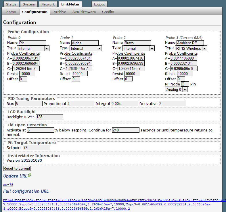
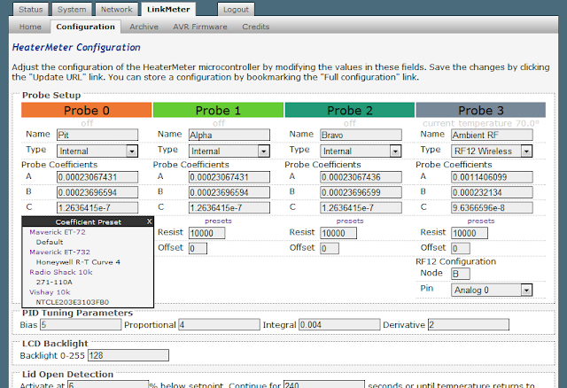
BTW...I have been playing with the new configuration page and it works really great! The web pages have gotten so good that you don't really need the LCD and button. You can just use your smart phone or PC.
 
Bryan,

How can I connect the Linkmeter router to my main router so I can use the internet connection with out plugging a cable into the back of the Linkmeter router?

I tried a couple times to add another wireless radio but I can't seem to get the settings right.

I want to open a port on my main router so I can access the Linkmeter remotely.

I know you have talked about this in the past but I didn't see any instructions on how you configured OpenWRT. I will keep playing with it but I am assuming this is possible.

Thanks,

DaveS
 
I was bored today so redesigned the board a bit so I could fit it in my WRT54G v3. I sent it to DorkbotPDX and it will go out tomorrow. This should fit insider some G, GS, and N models that don't have the L-shaped board (don't quote me on that yet). I removed the LED components from the board because I am going for a bare minimum type design. I am thinking of doing something similar while keeping the LED stuff but for now I am being selfish.

I am going to test the board and once I am happy I will make the eagle files available if anyone is interested. The idea is for the board to sit upside down on a male ttys1 header. There is a 8x1 female pin headers opposite of the ttys1 header to support the board. I put two options for serial port headers because I noticed different routers have their ttys1 pins oriented differently.

Here is an image:
MiniLink.jpg


Bryan, you get one for free...if you want one of course. I just hope it works. I have lots of experience with CAD type software so hopefully I didn't screw anything up too bad.
 
Bryan,
Had a couple of questions. In the parts list for the v3.1 board, you have the RFMB12. So you only need 1 of these on the board? How many wireless temp. probes can you connect at once? Where do I find the probes themselves?

Also, for someone just starting from scratch on this project, do you have any advice for where to start at? Do I goto the original LinkMeter thread or the HeaterMeter thread? Just looking for a process to follow.
Thanks in advance.
 
Status
Not open for further replies.


Back
Top