LinkMeter v2 Homebrew BBQ Controller - Part 1


Status
Not open for further replies.
Originally posted by D Peart:
pc0=1.14042e-3,2.32174e-4,9.61382e-8,0,2
Except because the thermistor is on the "FOOD3" line, you want the set to start with pc3=

For debugging, you may want to telnet/ssh into the router and run:
lua /usr/lib/lua/lmclient.lua

If you see "nil connect", the linkmeterd isn't running. Verify your /etc/config/lucid has the lines from the wiki and restart it.

If you see "{}", linkmeterd hasn't received any data from HeaterMeter, verify your physical connections and that `stty -F /dev/ttyS1` reports speed=115200

If you see data like

{"time":1322078848,"set":73,"lid":0,"fan":{"c":0,"a":0},"temps":[{"n":"Pit","c":75.4},{"n":"Food Probe1","c":null},{"n":"Food Probe2","c":null},{"n":"Food Probe3","c":null}]}

I dunno what's up but that's a place to start.
 
Originally posted by D Peart:
On that note we should give each probe a number as it is the four show the same when you first go through the menu.
The reason they all look the same is because they all load the same default. Adding the probe number added to the size of program, which was bad because there wasn't enough space. I'm concerned about adding it still because I still used the wishield version and you're going to have to change them anyway.
 
I got my probes today, the are replacement probes for the Maverick ET732. It looks like they are not the same as the ET73 because they are reading 8 degrees. Guess its off to measure boiling water
icon_smile.gif
 
Originally posted by Bryan Mayland:
<BLOCKQUOTE class="ip-ubbcode-quote"><div class="ip-ubbcode-quote-title">quote:</div><div class="ip-ubbcode-quote-content">Originally posted by D Peart:
Could you provide me a sketch that would allow me to just print a single character? I'll try to modify that to figure out what is going on with my LCD.
When debugging my LCD I used a sketch like this
<pre class="ip-ubbcode-code-pre">
#include <ShiftRegLCD.h>
ShiftRegLCD lcd(8, 4, TWO_WIRE, 2);

const unsigned char lcdBacklight = 5;

void setup() {
pinMode(lcdBacklight, OUTPUT);
analogWrite(lcdBacklight, 255);
lcd.clear();
}

void loop() {
lcd.print("A");
delay(5000);
}
</pre>
That prints "A" every 5 seconds which gives you a known set of data to look at. I'm really not sure how to debug an LCD problem without a scope, or even with a scope for that matter. I've looked at the data 10 different ways and still a working LCD and a non-working LCD look the same to me. For the 4.0 board down the road I'm going to try with a latched register running on the SPI bus which should get away from the problem entirely I think. </div></BLOCKQUOTE>

Thanks for the sketch. I'll give it a go and see if I can figure out what is happening. Hopefully I can tweak this to print two different characters and try to isolate which lines are having issues. As all the lines are good with an ohm meter, I'm really confused as to what could be wrong. I may have to dig out and dust off that logic analyzer, yuck.

dave
 
I ended up buying a WRT54GL...this is an amazing router!!! I wish I wouldn't have wasted my time messing with the other router. Just buy this one and dont mess with the others unless you are a computer programmer like Bryan.

I am testing my build now. My mount for the fan failed but I got an idea for a fix. The pit probes works fine but for some reason when I plug in the other probes all of the probes read really really high. When I plug in the other probes without the pit they work fine. I am sure this is a hardware issue. I will have to look into it after I am done smoking. All of my probe tips are grounded to pin 1 of the probe header. The non-tip (not sure what to call that) is wired to the other probe pins). I assumed that was the way it should be wired but I am starting to second guess that. I don't know...anyone else having this issue?

So basically my first test was a big fail on my part
icon_frown.gif
 
Dave S: The other part is called the "sleeve". You should be reading ground (J2 probe jack pin 1) on the sleeve, not the tips though.

Welp playing with everything with it powered up seems to have screwed me somehow. After shoring something, my /dev/ttyS1 no longer works. It is getting pulled high by something which prevents it from receiving any more. Son of a...

I'm out of town starting tomorrow morning until Sunday night, so happy thanksgiving guys!
 
Bryan,

What is diode D2 for? If we don't want QH driving E, just don't connect it? I looked at the 74LS164N datasheet and it just just the last register.

thanks,
dave
 
I have installed the V2 linkmeter software on my router. On the initial login I set the password. When I press save and update it just goes into saying waiting on router. Then when I reboot the router it acts like I never set the password. The next problem I am having is trying to figure out how to fix the configuration file like it says at the bottom of the wiki for updating from v1 to v2. I can't seem to get SSH to log in. I hope someone has some good info to get these problems fixed. Thanks in advance.
 
Originally posted by Duston Anthony:
I have installed the V2 linkmeter software on my router. On the initial login I set the password. When I press save and update it just goes into saying waiting on router. Then when I reboot the router it acts like I never set the password. The next problem I am having is trying to figure out how to fix the configuration file like it says at the bottom of the wiki for updating from v1 to v2. I can't seem to get SSH to log in. I hope someone has some good info to get these problems fixed. Thanks in advance.

If you didn't set the password, just telnet into the router instead of SSH.

dave
 
Originally posted by D Peart:
What is diode D2 for? If we don't want QH driving E, just don't connect it? I looked at the 74LS164N datasheet and it just just the last register.
D2 and R4 form an AND gate, meaning E doesn't go high unless QH and LCD_DATA are high. It is the "trick" that makes the 2-wire LCD mode work. It definitely needs to be populated or the LCD won't work at all.

Have you tried putting 2.2k resistor(s) in R8/R9? I know that helped Ed absorb some stray capacitance on his board that prevented it from working. I wouldn't solder them in, just insert one or both and see if it makes a difference.

I feel your pain about trying to desolder the shift register. It is incredibly difficult for me even with a solder sucker and copper braid. The RFM12 radios I've given up on removing after destroying 3 and their boards.
 
Originally posted by Bryan Mayland:
<BLOCKQUOTE class="ip-ubbcode-quote"><div class="ip-ubbcode-quote-title">quote:</div><div class="ip-ubbcode-quote-content">Originally posted by D Peart:
What is diode D2 for? If we don't want QH driving E, just don't connect it? I looked at the 74LS164N datasheet and it just just the last register.
D2 and R4 form an AND gate, meaning E doesn't go high unless QH and LCD_DATA are high. It is the "trick" that makes the 2-wire LCD mode work. It definitely needs to be populated or the LCD won't work at all.

Have you tried putting 2.2k resistor(s) in R8/R9? I know that helped Ed absorb some stray capacitance on his board that prevented it from working. I wouldn't solder them in, just insert one or both and see if it makes a difference.

I feel your pain about trying to desolder the shift register. It is incredibly difficult for me even with a solder sucker and copper braid. The RFM12 radios I've given up on removing after destroying 3 and their boards. </div></BLOCKQUOTE>

I actually populated R8 and R9 on all the boards, but I just removed them for the bad board, but it didn't make a difference.

I find that compressed air really helps blow molten solder out of small holes. Just heat it up till it is liquid and puff with a can of air. Be careful because the solder will to flying.

Clever on the AND gate, I was trying to figure out what R4 was doing.
 
OK I got V2 of the Linkmeter software installed correctly. I telneted in ans made the changes as stated in the bottom of the wiki for upgrading from v1 to v2. I am now trying to set a password and every time I input one it does not seem to want to take it and when I reboot the router and reload the page it just lets me log in with no password. I am sorry for all the Noob mistakes but I appreciate all the help.
 
Originally posted by Duston Anthony:
OK I got V2 of the Linkmeter software installed correctly. I telneted in ans made the changes as stated in the bottom of the wiki for upgrading from v1 to v2. I am now trying to set a password and every time I input one it does not seem to want to take it and when I reboot the router and reload the page it just lets me log in with no password. I am sorry for all the Noob mistakes but I appreciate all the help.

I am having the same password issue with the most recent openwrt build.
 
Well hopefully they will get it fixed soon. I would like to say that I have a heatermeter finally working with a wishield and it is currently running my new WSM 18.5. This is going to be a great Thanksgiving.
 
Originally posted by Duston Anthony:
Well hopefully they will get it fixed soon. I would like to say that I have a heatermeter finally working with a wishield and it is currently running my new WSM 18.5. This is going to be a great Thanksgiving.

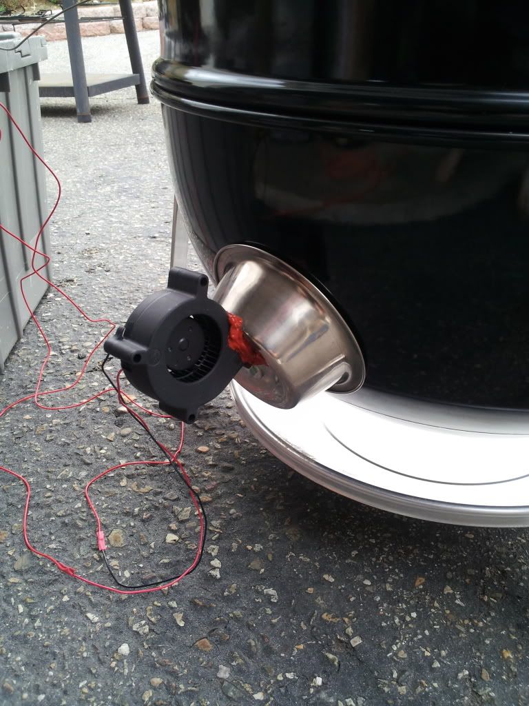
How did you mount the blower on your WSM? My first attempt failed.
 
Well I got these little 3" stainless steel dog bowl dishes and used on on the inside as a deflector and the other on the outside. I used a bolt with a wing nut to hold then in place. I then punched a square hole in the outside one and used some High temp RTV to seal all the little gaps around the blower. I will go outside in a few min and snap a picture of it.
 
Has anyone ever ran into a problem when you plug a UNO into a computer it does not even recognize a usb device. It is powering the board and the blink sketch is working because the led is blinking like it is suppose to be. I can't seem to be able to load an other sketch on to it.
 
Originally posted by Duston Anthony:
Has anyone ever ran into a problem when you plug a UNO into a computer it does not even recognize a usb device. It is powering the board and the blink sketch is working because the led is blinking like it is suppose to be. I can't seem to be able to load an other sketch on to it.

Sounds like the drivers didn't get installed correctly.
 
Anyone have an extra ver 3.1 board they would like to sell? I'm trying to build three systems, and two are working great, but I can't figure out what is wrong with the third. I have swapped all the components from working boards to the non-working board and they are all fine. The only thing I haven't tried yet is swapping the board.

I've spent long enough on this, that I'd rather pay $10 to someone for a new board and try that out. Let me know if you have an extra.

thanks,
dave
 
Status
Not open for further replies.


Back
Top