You are using an out of date browser. It may not display this or other websites correctly.
You should upgrade or use an alternative browser.
You should upgrade or use an alternative browser.
LinkMeter v2 Homebrew BBQ Controller - Part 1
- Thread starter Bryan Mayland
- Start date
- Status
- Not open for further replies.
Hi,
I'm trying to configure the Linkmeter using the web page.
I have two questions:
1. What should I use as the values (based on the ET-732 probes)?
I can select the probe type and it populates the Co-efficient A but what values should I use for:
<UL TYPE=SQUARE> <LI> Co-efficient B & C
<LI> Resist
<LI> Offset
<LI> PID Tuning Perameters (Bias, Proportional, Integral & Derivative) [/list]
2. I know it sounds strange but I can't seem to find the 'submit' button (or it's not working).
Can anyone help
Thanks
Nick
Bryan Mayland
TVWBB Hall of Fame
What browser are you using? When you select a probe preset it is supposed to fill in all 3 boxes.
All the rest the defaults are fine. Resistance is 10k, offset is 0 degrees, PID params you can jockey with only if you don't think it is doing a good job controlling your grill.
2. The instructions at the top say "Save the changes by clicking the "Update URL" link."
All the rest the defaults are fine. Resistance is 10k, offset is 0 degrees, PID params you can jockey with only if you don't think it is doing a good job controlling your grill.
2. The instructions at the top say "Save the changes by clicking the "Update URL" link."
Hi Bryan, thanks for quick reply.
Using Firefox but tried IE9 as well. It looks wierd... none of the boxes are filled in - the defaults are blank - this suggests something wierd.
BTW, Heatermeter serial output using FDTI is good... regular feed of data coming through and pit probe stable. When I connect via to the Router the Pit probe starts to drop out and return on a cyclic basis (not not envery 2 seconds).
What do I do to monitor the serial output from the router (SSH?) but what command?
I'm thinking of flashing the router again.. to see if something got screwed up given the defaults etc.
Shane Woessner
TVWBB Member
Just ordered yesterday so I will let you know when I get them. A friend said if you pay the regular $5 shipping you're looking at 3-4 weeks. </div></BLOCKQUOTE>Originally posted by Shane Woessner:
<BLOCKQUOTE class="ip-ubbcode-quote"><div class="ip-ubbcode-quote-title">quote:</div><div class="ip-ubbcode-quote-content">
I'd looked at iteadstudio.com before I made my first board because they have some pretty dirt cheap prices. How long was the turnaround time from submitting your design to the board showing up?
Received Email today that the boards have been mailed... now its up to the postal system. Pretty fast from factory I ordered Saturday so I'm guessing they received it Monday. Stay tuned!
Do DIP sockets normally come with the ATmega? I ordered one controller, but got 4 with no sockets.
No, they are separate items. It was missing from the Mouser component list until a few days ago but Bryan has now added it (and the button cap).
Bryan Mayland
TVWBB Hall of Fame
Yeah when you go to the configuration screen, it should all be filled in with values. If it isn't that indicates a communication problem between the HeaterMeter board and the linkmeter service.Originally posted by N Waring:
Using Firefox but tried IE9 as well. It looks wierd... none of the boxes are filled in - the defaults are blank - this suggests something wierd.
BTW, Heatermeter serial output using FDTI is good... regular feed of data coming through and pit probe stable. When I connect via to the Router the Pit probe starts to drop out and return on a cyclic basis (not not envery 2 seconds).
What do I do to monitor the serial output from the router (SSH?) but what command?
To see the serial output you need to stop the webserver/linkmeter service and cat from the device:
/etc/init.d/lucid stop
cat /dev/ttyS1
Unless you want to order another custom board from borkbot, you're best getting some 'stripboard' or other such prototyping board and making your own.How do I get a button board?
I'm up to the same stage as you... and am about to make up my own board. The only thing I have noticed is the strange foot spacing on the button itself... it doesn't seem to line up with the holes.
mmm... not managed to re-flash the firmware yet. I'll try that first.If it isn't that indicates a communication problem between the HeaterMeter board and the linkmeter service.
Shane Woessner
TVWBB Member
Anyone ever use IRC to chat about this project?
server freenode channel linkmeter
server freenode channel linkmeter
Bryan Mayland
TVWBB Hall of Fame
Yeah that's LuCI for you. It is incredibly slow on the WRT54GL and the problem amplified by the fact that when you commit changes, it launches other processes to do the work and then it goes into an almost-out-of-memory situation which grinds the whole device to a near-halt, sometimes killing the server process altogether.Originally posted by J Davis:
When I pull up the web interface, it gets slow after a few clicks, making it difficult to enable changes since I'll end up having to wait a few minutes to just log back in.
The server is also limited to a small number of connections at once which, if one or more is still busy committing a change, can prevent it from accepting connections at all. Increasing the number of connections causes out-of-memory crashes.
OpenWrt/LuCI is incredibly versatile and easy to code for, but really suffers for performance on this hardware/configuration.
I've built the HeaterMeter element and am having some problems integrating with the Router.
Initially looked like the router firmware may have been a problem... Unfirtunately something went wrong when tyring to reload firmware and now only get blinking power light. I'm sorting out a JTAG cable to try and recover before buying a replacement - but that's a different story.
Anyway, when powered via the FDTI cable, my heatermeter is pretty stable - i.e. with the probes connected the LCD displays the temperature properly and consistently.
However, with the Heatermeter powered from +12v (I soldered on the +12v power connector onto the heatermeter) it appears like the heatermeter keeps 'losing' the probes. Randomly, the LCD reports 'no pit probe'.
I'd be grateful for any guidance on why the difference when powering from the +5v FDTI vs. the +12v router power supply (connected directly to the Heatermeter)
Thanks
Nick
Andrew Meimann
TVWBB Member
Bryan,
Is there a way to use a wireless weather station (LaCrosse, Oregon Scientific) as a wireless probe for ambient temperature?
Is there a way to use a wireless weather station (LaCrosse, Oregon Scientific) as a wireless probe for ambient temperature?
Bryan Mayland
TVWBB Hall of Fame
I can't remember how I did it. I think I just put a piece of painter's tape on a CD, and put the button on top of that and put a dot next to each leg. Then I drilled a hole a little inside that mark and peeled the tape off:Originally posted by N Waring:
A quick question.. Before I drill some custom holes, is there any neat trick you've identified for creating a custom button board?
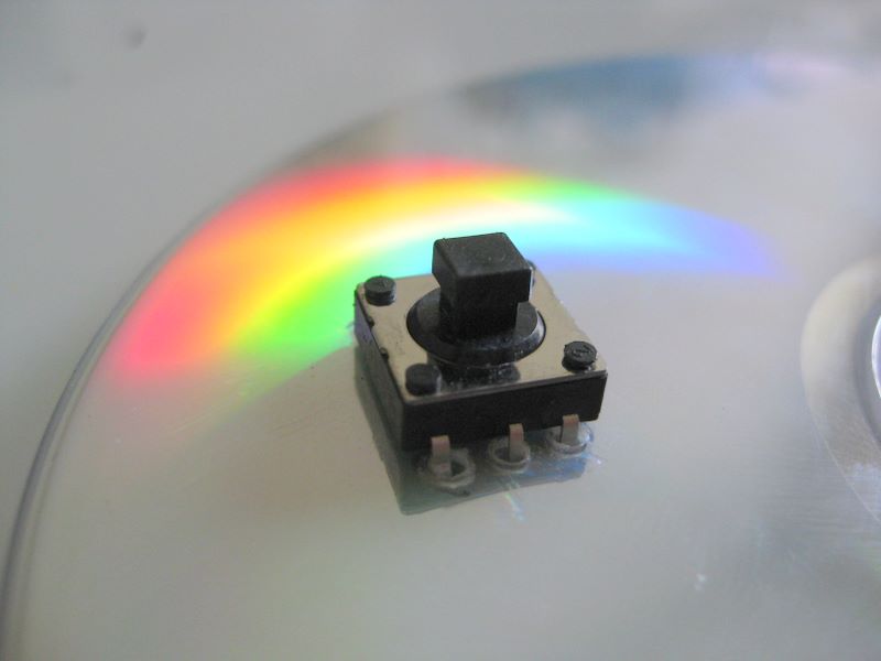
It worked first try, which is rare for me when building anything mechanical, so I assume I must have done it wrong and there is a much easier way to do it.
I need to move those photos up to the HeaterMeter picasa album...
Bryan Mayland
TVWBB Hall of Fame
99.9% of the time when you mess up your router, you don't need a JTAG to fix it. Usually you can still TFTP to 192.168.1.1 if you connect it through another wired hub/router and catch it just right during bootup. Remember, you need to use the BIN file when TFTPing.Originally posted by N Waring:
Initially looked like the router firmware may have been a problem... Unfirtunately something went wrong when tyring to reload firmware and now only get blinking power light. I'm sorting out a JTAG cable to try and recover before buying a replacement - but that's a different story.
Anyway, when powered via the FDTI cable, my heatermeter is pretty stable - i.e. with the probes connected the LCD displays the temperature properly and consistently.
However, with the Heatermeter powered from +12v (I soldered on the +12v power connector onto the heatermeter) it appears like the heatermeter keeps 'losing' the probes. Randomly, the LCD reports 'no pit probe'.
I'd be grateful for any guidance on why the difference when powering from the +5v FDTI vs. the +12v router power supply (connected directly to the Heatermeter)
I don't know why you'd lose connection when connected using 12V instead of 5V. You get that message also when the calculated temperature is outside a sane range (around 32F - 1000F) so it might have something to do with the probe cables getting ground noise on them from the 12V wall plug? The electrical side of this has me often scratching my head. It isn't rebooting (the AVR) when you see the probes drop out is it (the LED would blink)? Also maybe put a multimeter on the 5V line (pin 1 on the button connector is a good place to test +5V) and make sure it is a rock solid +5V. It might be off by up to 250mV but it should be completely stable.
Bryan Mayland
TVWBB Hall of Fame
There might be, but it will probably take some modification to the RF receiver to get it to work, and of course the software part. The problem is that our RF receiver is a robust FSK receiver and most of those wireless weather probes use a simpler OOK protocol.Originally posted by Andrew Meimann:
Is there a way to use a wireless weather station (LaCrosse, Oregon Scientific) as a wireless probe for ambient temperature?
If I knew now what I knew when I started playing with all these RF chips, I might have gone with using an OOK receiver as well. It still might be possible to receive though, with the current hardware.
- Status
- Not open for further replies.