LinkMeter v2 Homebrew BBQ Controller - Part 1


Status
Not open for further replies.
Originally posted by Brian Hilgert:
or i could just enable Lucid on startup by typing /etc/init.d/lucid enable
icon_redface.gif
Haha! You could but where would the fun be in that?

Good news everyone! I got my PCBs in the mail yesterday and I shirked all responsibility to populate one.
IMG_0537.JPG

IMG_0540.JPG


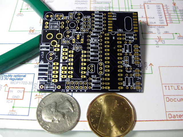
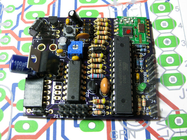
As you can see there are some problems with the silkscreening and a couple of the component outlines aren't the right size. The 50V cap on the left isn't the right voltage (but the proper uF rating) but it was what I had on hand. The actual one is a lot smaller. I'm also out of IRL510s so that's unpopulated. It was awesome I had the whole thing built start to finish in under 2 hours even after digging through component "grab bags" to find suitable parts.

The other problem of course is that it doesn't work. According to the oscilloscope, it does look like it is booting and getting partially through the hmcoreSetup() function but not completing. You may also notice there's no standard FTDI connector on this board which makes it hard to upload new code. I ran out of time last night and didn't get to fixing it but I learned a lot about component placement and starting to work on a troubleshooting procedure.

So for the next board PCB, I've got:
-- FTDI connector point
-- A screw hole and a cutout for mounting inside the original HeaterMeter case (for standalone use)
-- Convert the 2x5 LCD connector to 1x16 that matches the pinout of the LCD
-- Ability to mount both a 2.1mm barrel jack *and* the 12v pin header at the same time
-- Dimension change to 3.1"x1.8" to support RFM12B full 915MHz 1/4wave antenna
-- Space for optional 2.2k LCD pulldowns
-- Space for LCD current limiting resistor if needed

And fix whatever is causing this to not work!
 
it sure does look alot better then my homemade pcb though
icon_cool.gif


What I had problems with learning Eagle was finding the right wire connectors for the probes and fan. I did find the correct eagle part that you can pick up at the local radioshack.

Also, I did not quite understand some of the connections that eagle would do with the power supply components, so i tried to manually add the traces for them.
 
I flashed the ATmega chip in a different device then popped it into my new board and it worked! Sorta, the data was coming at regular intervals but the serial data was garbled. What could cause that? Well turns out one of the 16MHz resonators I got in a bag of 10 was actually 12MHz. Swapped that out and hooray it works!

Now of course my problem is that it doesn't boot until you send it serial data or apply 5V to the RX pin (pin 2 on the the avr). Sound familiar? Looking at it on the oscilloscope, it looks like it boots into the bootloader, waits one second then there's a short delay before it reboots. I'm trying to track down the source of this problem, which appears to be some sort of design flaw in the schematic if it is happening to not just me.

I'm out of town this weekend (these are my Friday test results), but I might have some time tonight when I get home to look more closely.
 
Good luck Bryan, I wish my Dad was still alive, he'd be able to help as he was into electronics for 50 yrs, fixed TV'S, was a ham and built his own stuff. I only learned and retained very little from him unfortunately.
 
Originally posted by Bryan Mayland:
I flashed the ATmega chip in a different device then popped it into my new board and it worked! Sorta, the data was coming at regular intervals but the serial data was garbled. What could cause that? Well turns out one of the 16MHz resonators I got in a bag of 10 was actually 12MHz. Swapped that out and hooray it works!

Now of course my problem is that it doesn't boot until you send it serial data or apply 5V to the RX pin (pin 2 on the the avr). Sound familiar? Looking at it on the oscilloscope, it looks like it boots into the bootloader, waits one second then there's a short delay before it reboots. I'm trying to track down the source of this problem, which appears to be some sort of design flaw in the schematic if it is happening to not just me.

I'm out of town this weekend (these are my Friday test results), but I might have some time tonight when I get home to look more closely.

I am very new to this project, but before I ask my questions I thought I would see if I can help with yours...If you haven't fixed the problem already, I would pull D4 or R22 and see if it isn't your soft reset circuit preventing things from booting correctly.

Now, to my questions. I have been reading through your code over the weekend, and I think I get the gist of it, but since I haven't written any software since basic C++ class over 10 years ago some of it is over my head, but I would really like to modify things to do 2 smokers at once.

The hardware part is easy, but for the software my first thought was to just duplicate code and have it run through everything twice, but that seemed clumsy, so I am wondering. Do you think I could pass a variable to your main functions that is set for Smoker 1 and Smoker 2 by an additional switch and then have the heatermeter file do a loop of (read button, hmcoreLoop(button))? I know this won't let me see both from the web page, but I can live with an 80% solution until you get to the bottom of your wishlist.

Lastly, I can't for the life of me find where you use the ambient temp, other than displaying/graphing it. Is this really necessary to the function of the system?

Thanks for all the work on this!
 
Yeah removing the reset circuit was the first thing I did, which worked! But then I unplugged all the 5 wires and plugged them all back in and it didn't work, so it turned out my testing methodology was flawed. Sometimes it just gets wedged running around 2-3V instead of 5V on VCC which is even more bizarre.

It is funny that you mention the 2-control system. I was actually thinking about this just the other night while I was going to sleep. The system is pretty hard coded to only having one control system. It is the sort of thing that if this were a standard client app running on a PC you'd think "Golly this guy sure is an idiot for coding it with that limitation" but really the problem comes down to size constraints again.

We don't have a heap, so there's no dynamic object creation. That means everything had to be statically allocated at compile-time. This was especially a problem for WiShield users because of the enormous RAM and PROGMEM requirements of having to also shoehorn in a TCP/IP implementation and an HTTP server. So if we say that there's no longer that restriction (but there still sort of is because I am maintaining backward compatibility) it becomes the classic programmer "0, 1, Many" problem and then I really start to overthink things. Especially configuration/EEPROM storage and then the website would be completely different and the CSV status would be different and the LCD display would be different, it is a pretty big deal to change from 1 to Many in a way that doesn't make me feel like a bad person for coding in such an embarrassing manner. Also, I'm out of Arduino pins so that would mean you'd have to decide between having an audio alarm or a second blower, so it impacts other things too.

And yeah the ambient temperature is just one of those things where I thought "Hey I've got a spare analog pin, might as well use it". The new LinkMeter schematic actually refers to this as "FOOD3", and has a jack which if you plug in a probe you get the probe value and if you unplug the probe you get the internal thermistor temperature.
 
That all makes sense Bryan, thanks. I was really thinking this might have to turn into a new "trunk" as it is somewhat of a specialized setup, but after reading your explanation I might have to abandon the software side of this as it sounds much more involved than my meager coding skills might be able to tackle.

As far as losing the alarm, looking back through the schematic again I think there is room to squeeze in some additional hardware that would enable sharing of the soft reset and the wireless LED so that those two pins are a 2 bit word enabling the latching of the LED, latching of an alarm, and latching of a circuit for soft-reset (which is actually the ATMEL preferred way of using the microcontroller to reset itself from what I was reading this weekend). That would require some code changes though of course and I would have to think of a way to "reset" the latches otherwise they would have to time out after a set period and the software would have to preemptively reactivate them.

In the end, maybe I will build two of these, one for each smoker...lol
 
What is this ATMEL-preferred way of resetting? I couldn't find a way to do it other than using the Watchdog timer to do a reset, but if you use the watchdog, you can't immediately follow it with a flash if you're using Optiboot. I can't believe they baked that in. Sure, you boot 1s faster after you flash new Arduino code, but *** who cares about that when you break the ability to reset-and-flash from software. I hope you're talking about another method because I would be happy to change to a non-hack solution.

The Alarm is also a PWM, which is needed to produce sound, which may not lend itself to being MUXed, but I am also interested to hear more about that idea.
 
I will have to look at your code to ensure that I am understanding your implementation correctly, but the only addition would be to use a timer circuit that is pulsed by your reset_not line. That will make it so that the reset pin is pulled low for a set amount of time. The concern that I read was as soon as you drive that pin low to reset the chip you lose control over the output and can't always guarantee that it will be pulled low for long enough to properly reset everything.

As far as the muxing of PWM outputs, I will toss some ideas to you this evening. I had envisioned more of a standalone 5v alarm vs. a PWM when I made my suggestion, but muxing PWM is doable as well. Just a little harder...Honestly, I will PM you some thoughts on what you might be able to do, but from seeing your hardware/software designs I think you know a lot more than I do and there are probably reasons that you have done everything the way it is.
 
Originally posted by Jon Schelmbauer:
I will have to look at your code to ensure that I am understanding your implementation correctly, but the only addition would be to use a timer circuit that is pulsed by your reset_not line. That will make it so that the reset pin is pulled low for a set amount of time. The concern that I read was as soon as you drive that pin low to reset the chip you lose control over the output and can't always guarantee that it will be pulled low for long enough to properly reset everything.
Oh yeah I looked at external circuits to do it with something like a trigger that propagated to an inverting one-shot pulse generator but it would an IC and a few support components and that was just way too large for our application. Correct, sure, but you need 20% more board space for something that you can implement much more cheaply and works 99% of the time.
 
Arduino Wifi Shield. It adds Wi-Fi communication capabilities to any Arduino. Instead of using any of the classic WiFi modules on the market we wanted to have something that will provide the maximum level of hackability to the user. The shield is based on a wifi micro module made by H&D Wireless coupled with a powerful AVR32 processor that carries the full TCP-IP stack leaving room to add your own protocols and customisations. We’ve also worked hard to make sure that you will be able to migrate your code from the Ethernet Shield with minor changes.
 
Originally posted by Bryan Mayland:
Oh yeah I looked at external circuits to do it with something like a trigger that propagated to an inverting one-shot pulse generator but it would an IC and a few support components and that was just way too large for our application. Correct, sure, but you need 20% more board space for something that you can implement much more cheaply and works 99% of the time.

Well, I can't PM on this board, so here you go -

I figured you had your reasons, and that's a very valid one. Additionally, as far as multiplexing the PWM outputs I think the cleanest way is again the addition of some hardware. A TLC5940 can be bought from SparkFun and is a fairly easy way to do that, although it is overkill to some degree, or even a second micro-controller. Depending on your desire to squeeze additional hardware in you could probably do it during your REV2 board by standing up the resistors/diodes, that saves about 50% of the real estate on each, or switching to 0805 or 0603 SMT parts. Those are big enough to still be easily soldered (realistically you could do down to 0402, but that starts getting tricky without a scope and a really nice iron) and would only add a couple dollars to the overall board cost.

I haven't given up yet, but my delusions of grandeur have definitely been tempered a little the last day or two, so I will probably go back to receive only mode and decide if I want to build a pair of these guys or hold out until I learn a lot more
icon_smile.gif
 
Originally posted by RJ Riememsnider:
Looks like Arduino is getting a Wifi solution: A simpler solution may be on the way......
Yeah I saw that yesterday too. The details are still a little sketchy, but it is nice to see that it includes a separate processor to handle TCP/IP but it seems like it might be based on the WiFly which didn't seem very good at being a server. I guess we'll have to see.

I don't know what to think about the Arduino folks. They are churning out a lot of garbage recently so I'm not exactly filled with confidence.

EDIT: There's still the issue of where to store the static content too, which means you'd need a SD shield on top of that and now the whole stack top to bottom is over 2" tall which is starting to make a pretty clunky device.
 
Originally posted by Jon Schelmbauer:
I figured you had your reasons, and that's a very valid one. Additionally, as far as multiplexing the PWM outputs I think the cleanest way is again the addition of some hardware. A TLC5940 can be bought from SparkFun and is a fairly easy way to do that, although it is overkill to some degree, or even a second micro-controller. Depending on your desire to squeeze additional hardware in you could probably do it during your REV2 board by standing up the resistors/diodes, that saves about 50% of the real estate on each, or switching to 0805 or 0603 SMT parts. Those are big enough to still be easily soldered (realistically you could do down to 0402, but that starts getting tricky without a scope and a really nice iron) and would only add a couple dollars to the overall board cost.
I do think that's getting a little carried away. The design is something that should be able to be built will all through-hole components by someone with modest soldering skills and a minimal investment. I'd also not like to resort to standing up all the resistors and diodes. It was something I tried to avoid in the design. I understand you're trying to include larger functionality but to me the benefits don't justify the drawbacks of adding more parts and complexity.
 
Originally posted by Bryan Mayland:
I do think that's getting a little carried away. The design is something that should be able to be built will all through-hole components by someone with modest soldering skills and a minimal investment. I'd also not like to resort to standing up all the resistors and diodes. It was something I tried to avoid in the design. I understand you're trying to include larger functionality but to me the benefits don't justify the drawbacks of adding more parts and complexity.
According to my friends I tend to get carried away on projects quite regularly, so I guess it was bound to happen
icon_smile.gif
I am actually one of those crazy people that would much prefer to build with all smt, but probably because that's what I have a lot more experience with and I have a Metcal at home with which to do it. Anyway, over the last couple days I think I have come up with a solid plan B though that I was going to bounce off you for some thoughts and then maybe move to a new thread once I am able to implement it.

I am thinking for doing multiple smokers one could buy a couple of your boards (once they are done), populate one fully and then use the power generation, clock etc... on that to feed a second "bare bones" implementation. From there either do two displays and two sets of buttons or have all of the headers for both boards go to a daughter board that can switch between which micro is being displayed/controlled. That won't let you see or interact with them both via the webpage, but that might be fixable later in the OpenWRT code.

I think with the cost of hardware that would be needed on a second PCB this approach probably won't be a whole lot more expensive than adding in extra ICs etc... to MUX the pwm outputs and would keep the project geared towards the majority of the single use folks.
 
Originally posted by Jon Schelmbauer:
According to my friends I tend to get carried away on projects quite regularly, so I guess it was bound to happen
icon_smile.gif
I am actually one of those crazy people that would much prefer to build with all smt, but probably because that's what I have a lot more experience with and I have a Metcal at home with which to do it.
Haha yeah I hear that! This project started as a "low-cost alternative to the Stoker system". I wanted basically a Stoker with WiFi but the base stoker was like $350 and you still had to tote out a wireless adapter too. Since then I've bought well over $1000 in equipment and parts, and spent hundreds of hours on development. It has become my indoor hobby though so I guess it is a lot cheaper than some other alternatives (e.g. hookers and blow).

I'm not at all comfortable with SMT components but I do appreciate their benefits. I'm just trying to keep everything through-hole and somewhat simple because most don't have backgrounds in circuits or software. I'm excited to see what you come up with!
 
Bryan, I agree with almost everything you said buy feel the need to bring up the point the hookers and blow could be an indoor or outdoor hobby.
 
Hahah point taken, RJ. Just to keep you guys updated, I've been slowly desoldering and removing components from my PCB then testing to see if it makes a difference. A tedious process, but I've removed well over half the components and I'm still having boot-up troubles. I'm running out of possibilities! Hopefully I find what's wrong before I run out of components on the board.

Something strange I've noticed (I'm using the 'blink' sketch to test with, with the pin changed to D9). The standard "not working" sequence is:
-- Optiboot starts the serial (raising pin 3 to 5V)
-- Optiboot blinks pin 19 (D13) twice
-- Optiboot times out and lowers serial line as it boots to user code
-- A couple hundred milliseconds later, Optiboot starts again.

When I connect a serial line and send a byte of data:
-- Pin 15 (D9) blinks quickly
-- The above Optiboot sequence occurs
-- User code actually runs this time

The odd thing in that is that pin 15 blinks before it boots (or rather at the end of the previous boot). Exceptionally strange because pin 16, 17, 18, and 19 do not which are all PORTB pins so it isn't like the chip is setting them all high for a brief moment. I should hook up the scope and see if they are going high but for just a really short amount of time...
 
Status
Not open for further replies.


Back
Top