Just built my first Heatmeter...booting with USB, not with 12V


Kris Pfeiffer

TVWBB Member
Hi.

I received the AWESOME case on Friday from Tom and put the finishing touches on the electronics this morning. I plugged it into a USB power source, and the HM booted fine...the display shows "NO PIT PROBE" and the temp of Probe 3 (the ambient temp).

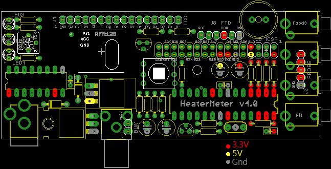
When I plug the RPi into a 12V (actually a 9V) source, all I get are the three LEDs lit up all the time and nothing else - nothing on the LCD, etc. I do the LCD change a bit - one row of very very dark blocks, but that's it. I've fooled with the LCD contrast as well.

I'm guessing this is a problem with the 12V power supply side. Any idea as to why all of the LEDs are lighting up?

Where do you recommend I start debugging this thing?
 
Last edited:
Ok, while on my quest to determine what I did wrong, I read some messages about the power supply side. I then discovered that I installed the MOSFET backwards. I reversed it, but I'm still getting the same problem. Have I fried out part of the board now?
 
I don't think reversing the MOSFET would be a problem if you never plugged in a blower. The gate would have been tied to ground so it wouldn't conduct, and the body diode should have prevented 12V (9V) from being backfed into the microcontroller. In theory.

I can't really help you diagnose it other than to make sure all your solder joints are good and the parts are facing the right direction. Every instance of someone having a problem when on the 12V power was one of those two things. This diagram might help you determine if something's not right
hmpi-power.png
 
I never did plug in the blower. While putting things together, I did have a problem with soldering the power supply caps (I had them switched around).

That will be helpful. Now I have to work all day before I can get home and test everything out. Darn work.

- Kris
 
After reading troubleshooting threads last night, I did go back and retouch a lot of solder joints. I think I can feel safe that the microcontroller is ok, as it will still boot via the RaspPI USB power input and still displays the current Probe 3 temp on the display. I'll go back tonight and test all the voltages.

How picky is the device as far as the input power goes?
 
Picky in what respect? It will take anything over 7V and make what it needs out of it. If the LCD still has words on it, that means the two most sensitive parts are working fine, the ATmega and the shift register IC. The capacitors can be damaged if inserted reverse polarity. They could just not work as well (reduced capacitance) but that would be nearly impossible to tell unless there was some sort of stability issue.
 
Picky in terms of the supply side voltage and amps...I'm using a 12V 1.5A supply...my guess was, and I think you've affirmed, that I'm ok with that.

Sorry for the lack of electronic understanding...I'm trying to work on it. This project will hopefully help.

I didn't install the caps with the wrong polarity...instead, I installed them in the wrong place (one was switched for the other). I discovered this far before I ever turned the thing on, so those caps are fine now.
 
Yup the power supply just needs to be between 7V and 12V, 1A or more. At 7V the fan would probably barely turn on even at 100% though.

Misunderstood what you said about the caps but sounds like you got it sorted out.
 
Ok, I've made some progress. I don't mean to be verbose, but perhaps my fumbling about can help somebody out in the future as they try this.

Scratch the resistors - I put the multimeter to them and they appear to be all in the right place. I'm not sure what's with the colors, but the resistance is ok.

I checked pins coming off IC1 - there was a flakey connection. I'm not get around 5V where I should, but for some reason I'm getting 4.06V where I believe I should get 3.3V. For instance, if I check the 3V3 header pin that comes from the RaspyPI, I get 4.06V.

Weird Ground Thing: if I use the RaspyPI GND pin and check the other RaspyPI pins that should read 3.3V or 5V, I get nothing. If I use a different ground (e.g., the MOSFET's ground pin), I get the right (well, I still get the 4.06V) from the RaspyPIs pins. I"m not sure if this is relevant, but when everything is powered off and unplugged, I get continuity between the RaspyPIs Ground Pin and the other pins that should be 3.3V or 5V. Perhaps most disturbing (hopefully helpful?): If I use the MOSFET's ground pin as ground and check the voltage at the RaspyPI's Ground pin (really, the pin on the HM board that mates up with the RaspPI's Ground Pin), I get 3.28V. Could this indicate I have a short to ground somewhere on the HM board? Indeed, the only place on the board that seems to have the 3.3V is somewhere I don't think it should be - the ground pin from the RaspyPI.
 
Last edited:
I've been debugging the board for the last several nights. I'm bleary-eyed as I strain to find a solder whisker or something that could be causing this. I'm using a big magnifier that I have on my workbench, but I'm stepping up to a jeweler's loupe.

I have a question about my conclusions...I have the 12V plugged into the HM board and it's powered on. I've concluded that I have a short somewhere because when check a few points on the board that should be ground, I see 3.3V instead. They're not all like that...just some. Meanwhile, when I plug the PI's power supply in and power up, everything works just fine - the menu, the buttons, even the probe temps. Only when the 12V is plugged in is there a problem.

1. Am I right to assume that there should be no current when I check all of the points on the board that should be ground?

2. Since the problem seems to appear only when the 12V is plugged in and, when that's unplugged and powered by the PI, the problem is in or around the power supply.

3. If a component (cap, diode, transistor, etc.) failed, could this theoretically cause the problems I'm seeing?


Again, sorry for the never ending questions. Bryan, your patience and help are appreciated.

Thanks,
Kris
 
Hard to tell exactly what you may have going on here, some close up high res pictures would help us inspect your board to spot any errors in component placement or soldering. Even for your own inspection, pictures are great, cause you can zoom in on them on your screen and see really good. (just try to make sure they are not dark or blurry)

The power scheme in the HM system is a little odd.... The 12V powers the blower and also the 5V regulator, the 5v from the regulator powers the rPi, the rPi in turn puts out 3.3v that is used in the HM board. (alternately there is a 3.3v regulator on the HM board that supplies 3.3v for standalone operation).

It's tough to make sense of the info you have given, for instance, a ground should bring ANY voltage down to zero if there is a short to a power pin (and probably burn something up or at least make your PS shut down). So there shouldn't be any voltage on ground pins anywhere... All grounds should be connected together, so you can start out by removing power from the HM and the rPi and checking CONTINUITY between grounds, they should all be connected together, you meter should show no resistance between the various ground points.

I would suspect you have a solder bridge somewhere, or a blown or backwards diode or transistor. Like I said, take some close up pictures of your board (front and back) and post them so we can zoom in and inspect your work, that would be a good place to start...
 
Yeah everything labeled ground should have 0.0V and read < 1 ohm to any other ground pin. I've never used the MOSFET as my ground point, but make sure you're using the Source pin, not the Fan's "ground" pin which isn't grounded. I always use either of the ground pins from the FTDI or Probe connectors as my ground when doing testing.

You might try taking some high resolution well-lit photos of the board (use a flashlight if you have to) and posting them, as it is sometimes useful to get another set if eyes on it. I also see things in photos I can't see normally. There's not a whole lot of circuitry from the 12V input to 5V output so it shouldn't be that tough to pin down. The 5V regulator is a pretty complex little nugget though.

Are you powering just the HeaterMeter board by itself with the 12V? That's the best place to start, then check all the 5V spots to make sure they're 5V.
 
Thanks for the great advice.

I think I'm getting close to finding the problem. To be honest, I could probably poke around on the thing for hours and not solve anything...it's the expertise here that's guiding me...and I'm betting this could be a big clue.

Before that, however, when I power up the HM board without it attached to the PI, I'm getting 5V in the locations that should be 5V when I use the ground on the voltage regulator (POINT B, shown in the diagram below). Ground C and A show the same. However, if I use any of the other grounds (D through M, again, see below), I read 3.15V where it should be 5V.

I took your advice and started to check continuity / resistance between different ground points. Curiously, if I touch the right two ground points, one of the LEDs lights up...and of course, there's no continuity. It seems that part of the board is doing this - not the other. I'm guessing that somewhere therein is the solution.

Here's a diagram of the grounds, which each one labeled a different letter:


grounds by k_pfeif, on Flickr

Grounds A, B, and C show continuity with each other. The others: D through M, have continuity amongst themselves. A, B, or C show NO continuity with D through M.

I shot some macro photos of the board. The cloesups make it look ugly, but honestly, it looks better in person. Obviously, however, there's a problem somewhere in there. The Flickr Photoset is here - http://www.flickr.com/photos/kpfeif/

Here's an example shot from the set:


IMG_6373 by k_pfeif, on Flickr


I'll continue to hunt around. I see the little solder whiskers on the closeups - you're right: photographs really change your perspective on the board, especially the closeups.


Thanks again,
Kris
 
Take rubbing alcohol and an old toothbrush to all the solder joints. Any solder joint not shiny is a cold solder joint. This will also clean up the rosin from the solder core. Take your time. Once the board is clean clean clean, you will find it easier to see any solder bridges.
 
You should take a close up high res pic of the ENTIRE front and ENTIRE back of your board and post them both (in high res). With that we can open the pictures and zoom in and scan the board to try and spot potential problems, what you have posted here is just a tiny bit of what need be inspected....
As for measuring continuity of grounds, I would do that with the power disconnected.... I don't understand what you mean by grounds a,b,c etc? Do you have the 3.3V regulator installed? (IC4 I believe) If so, I would disconnect the rPi, power the HM with the 12V supply and check the voltages that way. Test for 12V, then 5V, then 3.3V.... Look for solder bridges where one trace or solder joint may be connected to another (where they shouldn't be)
 
Grounds A, B, and C show continuity with each other. The others: D through M, have continuity amongst themselves. A, B, or C show NO continuity with D through M.
This is some craziness going on right here. It makes a little sense though in that there are two halves of the board, and their grounds go through the ground lead hole on C1. Both B and C are in one ground pour and that is connected to D, which is supposed to pull the ground up through the board and take it to the other side.

You can try retouching the solder at point D, or removing the capacitor entirely (which serves only to smooth out the voltage going to the fan so you can run without it), or running a wire directly from B or C to D like so:
 
Whoa! Gentleman, I think I may have a Heatmeter...


IMG_0823 by k_pfeif, on Flickr

I cleaned it up with rubbing alcohol, let it dry, then, as you can see in the photo, I soldered a wire from the cap to the power regulator. I plugged it into the 12V and poof! Things look like they're up and running! I was too excited to the computer and post this message than to give it a thorough test, but hey, it's powered up and appears alive. I need to be sure I didn't bridge the two pads when i wired it up, but I think it's looking good. I'll plug it into the network and get all of that configured.

I can almost taste that brisket now...and of course I want to build another one of these...

I'm crossing my fingers by sending this already, but a HUGE THANK YOU to Bryan and everybody else who's helped me out with this. I went through highs and lows - first I didn't think I could do it, then I was confident, then I thought I was defeated...again, thanks to all of you it looks like I've got a working Heatmeter!

Thanks again,
Kris
 
Woohoo! Yeah I don't know how that's happened, but good work making the realization that the two ground planes weren't connected.


Back
Top