it was going so well..... any tips on de-soldering?


Tim Loftus

TVWBB Member
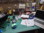
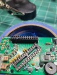
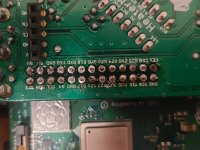
So I was building my new 4.3 HM on this rainy afternoon and it was going amazing. Then I smelled burning plastic, but didn't think much of it as sometimes I catch the soldering iron on the magnifying glass of my third hand. then I noticed........I had melted the side of the Pi header.
crap....
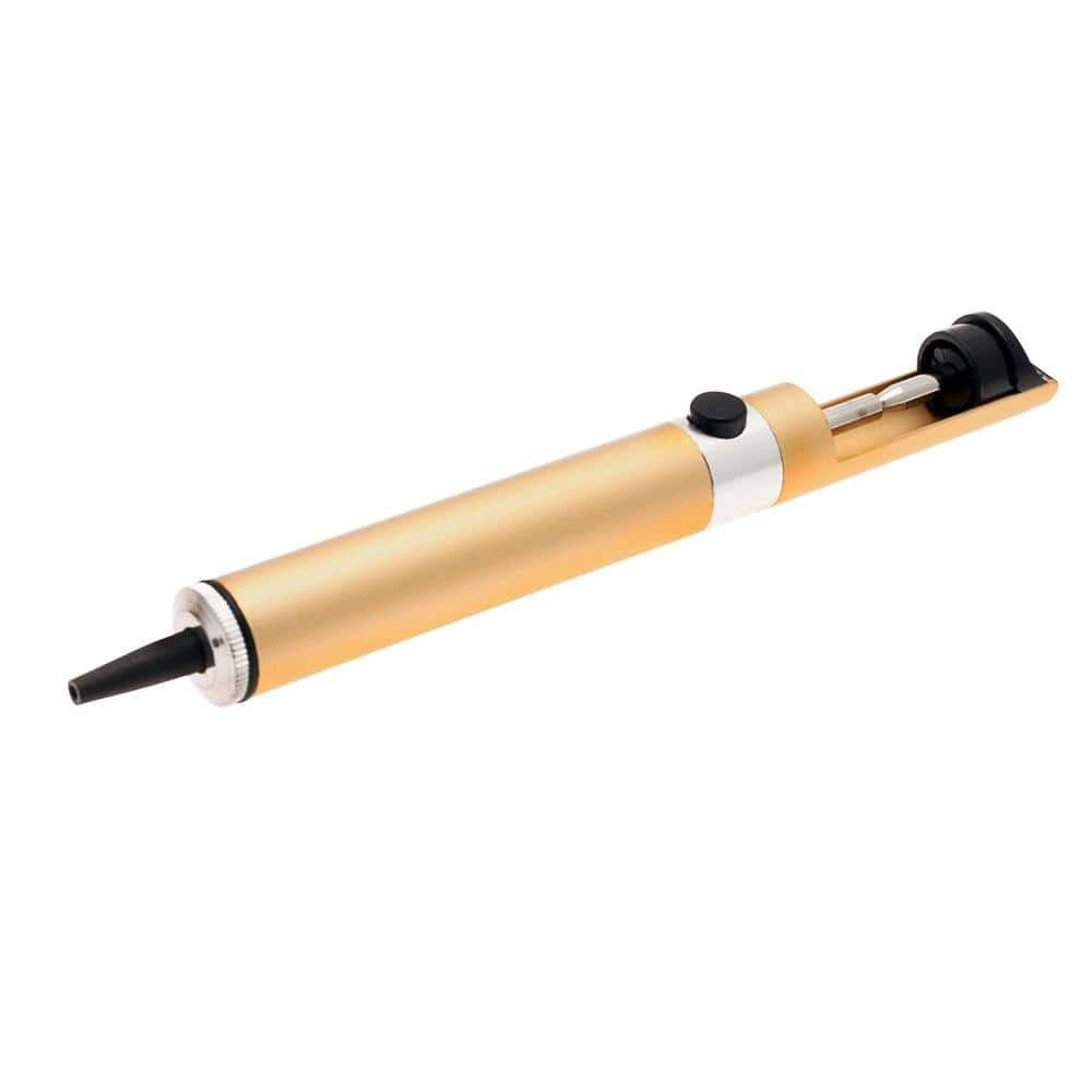
any tips on how to remove the header other then youtube, which i am off to now?
PS... Bryan, thank you again for the Heatermeter! this is my second one, I built one 5 years ago and until last weekend was awesome. I had one port go out over the summer but last week the thermocoupler went out. so time for a new one....which I had been wanting anyway.
out of curiosity how many HM have you sold?
 

Attachments

  • bench.jpg
    bench.jpg
    194.2 KB · Views: 34
  • heatermeter damage.jpg
    heatermeter damage.jpg
    162.4 KB · Views: 35
To the best of my knowledge, they sell a flat, tape-like product to de-solder with, but I have never used it.
 
To the best of my knowledge, they sell a flat, tape-like product to de-solder with, but I have never used it.

another option is this desolder pen device. You press down the pen to load it and then you melt the solder. Put the pen tip next to it and press the button which creates a vacuum to suck up solder. I preferred this over the tape myself.

 
you are both correct! after watching some videos I ordered a heated desoldering gun, and more soldering wick. if the gun works as well as the review say I should be good to go.
I'm jsut really bummed, I was hoping to have it up and running by tonight.
 
Oh dang that's a tough one, because it melted the RX and TX sockets, which are the top 4 pins we use!

I've used a desoldering heat gun before to remove some components and it works ok, but you have to be careful of overheating the other components or the board itself and peeling off the copper layer. One trick you might try if it doesn't appear to be going so well is to use some aluminum foil with a hole cut that's the size of the connector (to block heat getting to the other parts) then heat the *plastic side* of the connector until it starts to melt and get soft, then grab it with pliers and pull the plastic off, leaving the pins behind. Without the plastic holding them together, it becomes 2600x easier to remove the pins one at a time than to try to get them all off at once.

If you need a new 26 pin connector, I can get you one at just the cost of shipping, about $4. Just email me at heatermeter at capnbry.net. You may want to wait until you get the connector off just in case any of the other parts are damaged in the process and I'd charge you at most my cost for anything you need.

It is hard to say how many kits I've shipped between all the versions. For some reason the store doesn't track it, but I'd say probably in the ballpark of 2000 if you include kits, soldered, and circuit boards! Pretty great considering I didn't think anyone would want to buy a kit since they could just get the parts themselves from the parts list.
 
It looks to me like you could salvage that header. Use a drill bit to gently open the tops of the holes and then smooth out the top just don't go too deep that you hit the pins. I would try that first before trying to unsolder it it can be tricky to remove that many pins without damaging the board
 
Thanks Bryan, I have already ordered the replacement header, I also ordered the blue on black LCD Screen. I had that color on my old heater meter and loved it, so I figured why not.
thanks for the advice on the removal, I thought about taking a dremal to the top of the header and cutting it off, however heat gun might work well too.
And GS, I probably could salvage it it I really wanted to and had no other options but spare parts are readily avaiailable, so why not learn how to de solder?
 
Fair enough, I figured you had nothing to lose by trying. Good luck on your repair, should not be too bad, just takes some patience.
 
OK, maybe not the popular choice but because I am a lazy slug... and HATE to de-solder way more than I should. I would, given the ridiculously low prices of the components involved, chalk the mistake up to fate then merely buy a replacement. Then I would go sit in the shade by my pool, having a beer, and enjoying all the time and effort I saved.

But I am a lazy slug. YMMV

Tom
 
You should be able to wedge something between the black pin header shroud and the PCB, letting you pop off the black housing, leaving all the pin headers exposed. You can then remove each pin one by one and then use some solder braid or a solder sucker to remove the solder from the holes. Pop in a new header and solder it into place.
 
It looks to me like you could salvage that header. Use a drill bit to gently open the tops of the holes and then smooth out the top just don't go too deep that you hit the pins. I would try that first before trying to unsolder it it can be tricky to remove that many pins without damaging the board
This would be my first approach as well. The burn doesn’t look that bad to me. I would start by trimming off the melted plastic and then maybe some X-acto clean up work in the sockets.

Used to have a hot air desolder station. That’ll Spoil ya...
 
The "pin by pin" suggestion that Bryan made is good advice....

Since the HM has a double sided board there is likely solder on the top side of the board under the header as well as the solder side, when the solder looks to be removed on the solder side the pins may still be soldered on the top side.

So, after you de-solder by whatever means, rock the header and watch the pins in the solder side, if they all wiggle you are probably good, if some pins don't move you are still soldered there...

With so many pins it might be hard to get them all clear at once, so removing the plastic shell by whatever means will enable you to work on the problem pins one by one, on both sides of the board.

You can take some snippers and crack off chunks of the plastic header if your heat treatment doesn't do the trick....
 
so I wanted to update everyone, and also lean on everyone for additional troubles.
I go the new part and was able to do the pin by pin removal that was talked about. I played around with a copper wick for a bit and that did not work well at all. my heated solder sucker got cancled so I tried the manual one I had where you heat the solder with your iron and then pres the button. it took a few attemps to get it but once I figured out how to do it, it worked like a charm., so to anyone reading this in the future... get the solder sucker makes the job so much easier.

Now onto the other issues. I got my board finished and up and running, kind of. I isntalled win 32 diskimager and downloaded the latest stable release, and and loaded it on the card. I could not get connection to the pi or HM at all. on the pi I just get a red blinkign light. I saw on another thread that another user had the same issue and they downloaded the development release, and that worked.
that worked for me too.... I can now go to the heatermeter /devices page and se my HM however it says : HM not communicating.
when I go to the actual ip address it comes up and I can log in to the HM but I can't get to the confg screen. I have to flash the AVR Firmware. once I do that (online rep and choose the latest) I can finally get to the config screen.... but I can't save any changes. save and apply does nothing. its like I am not even clicking on it. I can reboot the avr, but that is it.

so did I fry my board, or I am missing a step?
also here is an after pic of the repaired part.....
 

Attachments

  • pi connector.jpg
    pi connector.jpg
    134.1 KB · Views: 7
  • HM pg1.png
    HM pg1.png
    24.8 KB · Views: 7
Well, that's some progress at least!

Sounds like there's an issue between the RX/TX on the Pi header and the ATmega chip (or the ATmega isn't operating normally). On the Configuration webui page, any field that is blank can't be edited because the value wasn't received by the Pi from the HeaterMeter. That would do what you describe where you change the value (from blank to something) and the webui won't take the change because there's no value for it to change internally. If your Configuration page has blanks in it when it comes up, then that's what would cause that. If that's not the case then you'll need to get more specific about what exactly you're changing and what the state of the page is (i.e. does the "Update URL" start to grow as you make changes).
 
Ok so I go the rest of the HM finished (LCD Board) and it is on and working, but still having the same issues..... do you think the AT Mega board is bad? should I order a new one? or could I have fried the HM board when I was tryign to repair the Pi header? what can I do to test?

Go to here and click on the ip address on the HM.
HD Devices pg 1.png
here is the home page where I can click on the configuration
Home page Pg2.png
go to the log on screen and log in. ...
here is what I see....
config home pg 3.png
rebooting avr there is a pop up saying rbooting avr, and I have to close the pop up.. but no cahnge.
so if I go to See AVR Firmware and then go to online repository
here is the screen. I usually click on the top one snapshots/trunk/heatermeter.hex Oct9 2020
and click flash.
flash pg 4.png
here is the output
Downloading 'https://heatermeter.com/devel/snapshots/trunk/heatermeter.hex'
Connecting to 18.234.176.243:443
Writing to '/tmp/hm.hex'

/tmp/hm.hex 100% |*******************************| 71625 0:00:00 ETA
Download completed (71625 bytes)
Stopping LinkMeter OK

LinkMeter platform is BCM2708
Loading SPI modules...
AVR fuses ffd705 OK

e863c068c3004b13e2728ee092e818e2 /tmp/hm.hex
hmdude: compiled on Oct 13 2020 at 15:11:31
Using port: /dev/spidev0.0
Loading ihex file: "/tmp/hm.hex" (25458 bytes)

0% | | 0 (0.0s)
0% | | 0 (0.0s)
5% |## | 1274 (0.1s)
10% |##### | 2546 (0.2s)
15% |####### | 3820 (0.3s)
20% |########## | 5092 (0.3s)
25% |############ | 6366 (0.4s)
30% |############### | 7638 (0.5s)
35% |################# | 8912 (0.6s)
40% |#################### | 10184 (0.7s)
45% |###################### | 11458 (0.7s)
50% |######################### | 12730 (0.8s)
55% |########################### | 14002 (0.9s)
60% |############################## | 15276 (1.0s)
65% |################################ | 16548 (1.0s)
70% |################################### | 17822 (1.1s)
75% |##################################### | 19094 (1.2s)
80% |######################################## | 20368 (1.3s)
85% |########################################## | 21640 (1.3s)
90% |############################################# | 22914 (1.4s)
95% |############################################### | 24186 (1.5s)
100% |##################################################| 25458 (1.6s)
Update successful
Starting LinkMeter OK

I can now see a configuration tab at the top
here is what it looks like.
linkmeter config home pg 5.png


so I can change various options. as you can see nothing is change or updating.
config changes pg 6.png

clicking on save and apply does nothing.
clicking on reset to current does nothing.
reboot AVR it says it does it but I don't notice any change.
if I click to Home to see the home page, and then back to the config page
here is what I see...
config after home pg 7.png
and some bonus pics of my HM....
Pi on.jpg HM Front.jpgall board back.jpgall boards.jpgboard.jpgRepaired header.jpg
 
Ok great detail in your explanation there. All the fields in the configuration page are blank, which means you can't edit them because the page can't tell where to put the data (it relies on the configuration structure coming from the HeaterMeter to know how to return the values). The configuration is downloaded as part of the startup of the Pi's linkmeterd daemon and that doesn't appear to be working. The reason it sort of works right after you Flash AVR is because HeaterMeter sends the version number as part of its own startup, and linkmeterd hears that, but can't complete the needed config download.

What that tells me is that you've got a bad connection from TX on the ATmega to RX on the Pi. Without the boards powered, measure from the physical pin 3 on the atmega chip itself (labeled as TX on base board, but don't measure from there) to the 5th Pi pin on the underside of the Pi itself (labeled RX on the base board, but again measure it on the Pi, not the labeled pin). Make sure you've got continuity between the two. Odds are you're not going to get a beep out of the multimeter here. If it doesn't then try testing the same thing between the labeled pins on the base board and that will tell you exactly where the problem is. If it does show continuity in the first test, then I'd lean toward the Pi's RX being bad somehow and try swapping in another Pi if you have one, or jumpering the RX and TX pins together without a HeaterMeter and trying to do an echo test on the Pi if you don't.
 
well I have great continuuity on the first test.... "measure from the physical pin 3 on the atmega chip itself (labeled as TX on base board, but don't measure from there) to the 5th Pi pin on the underside of the Pi itself (labeled RX on the base board, but again measure it on the Pi, not the labeled pin)."
I have two pi's that I can test with, but not sure either will work... the first is a brand new pi 4 model b. but I though somewhere that I read I can't use a pi 4.....
and a pi 1 that i am using with my other HM. (that I think was a pi b, but not sure. I had to cut off the video port or svideo port on it.
 
BRYAN FROM THE FUTURE HERE: I told you the wrong pins to check continuity. It should be Pin 2 - RX on the ATmega to TX on the Pi (4th pin in). All the stuff below is only if that also has continuity like the Pin 3 - TX / 5th pin RX you've already measured.

Well that is surprising. All signs point directly to that connection not working at all. You're right that a Pi4 won't work (it doesn't fit together with the HeaterMeter), but the Pi1 will. You'll have to switch to the other firmware though (select Snapshot, Pi A / B / etc from the two dropdowns on https://heatermeter.com/dl/) for it to boot.

You can also try SSHing into your current setup and manually trying to get a config dump using these commands
Code:
/etc/init.d/linkmeterd stop
cat /dev/ttyS0
Now you should see this scrolling by, except with different numbers, once per second
Code:
$HMSU,80,U,U,92.3,86.2,0,0,0,0,0*3F
$HMAR,0,0,0,0,0,0*16
$HMSU,80,U,U,92.3,86.2,0,0,0,0,0*3F

So far so good? SSH in again to get a second window open and this time enter this
Code:
echo /config > /dev/ttyS0

You may need to send it twice, but on your first window now you should see a dump of a ton of configuration settings
Code:
$HMSU,80,U,U,92.5,85.8,0,0,0,0,0*30
$UCID,HeaterMeter,20201009B*35
$HMPD,0.00000000,5.00000000,0.03000000,7.00000000*10
$HMFN,0,100,90,205,16,100,50,50*04
$HMPN,Pit,Pork,Pork2,Outdoor*3C
$HMPC,0,2.4723753e-4,2.3402252e-4,1.3879766e-7,5.0000000e0,3*3A
$HMPC,1,7.3431401e-4,2.1574368e-4,9.5156869e-8,1.0000000e4,1*30
$HMPC,2,7.3431401e-4,2.1574368e-4,9.5156869e-8,1.0000000e4,2*30
$HMPC,3,7.6253948e-4,2.0959136e-4,1.3193728e-7,1.0000000e4,2*3F
$HMPO,0,0,0,0*1A
$HMLD,6,240*0D
$HMLB,0,255,13,10,11,0*3A
$HMAL,-40,-75,-40,-135,-40,-110,-40,-200*3F
$HMRM,,,29,42*17
$HMSU,80,U,U,92.5,85.8,0,0,0,0,0*30
$HMAR,0,0,0,0,0,0*16

But I am guessing you won't see this, because the TX from the Pi to the HeaterMeter isn't working. Oh snap I told you the wrong pins.
 
Bryan, thanks for the reply and the update. You were correct the "new" test I do not have any connectivity. so I am guessing that the connection betweeen Pin 2 - RX on the ATmega to TX on the Pi (4th pin in) is broken some how. I am guessing where i soldered the new pi connector in. I do have connectivity from the underside of the HM board to the top of the Pi board for the TX. can I just solder a little wire from Pin 2 - RX on the ATmega to TX on the Pi (4th pin in)? I know it is probably not that simple, but what are my options?
HM board fix.jpg
 
It really is that simple. They are directly connected with nothing in between so you should be able to just solder a wire. That assumes you have continuity between the Pi board and the top of the HeaterMeter board where the Pi connector comes through on that pin. If you don't that will certainly make it more complicated to connect them. You'd probably have to mate the two boards, then run a wire from the TX pin on the HeaterMeter to the Pi's underside and solder the wire directly to the Pi itself.


Back
Top