Heatermeter build issues


Dave R

TVWBB Fan
Hi Everyone. I just finished building my first heatermeter 4.2.4. Using an old Sandisk sd card (512 MB). Using the usb to power on the rPi when connected to heatermeter board. I only get blocks in the top row of the LCD. Second row has nothing in it. After 'power on', I see the lights on the rPi blinking. The yellow and green LED on the HM are constantly lit(never see the red one come one, if it is supposed to). I checked my solder joints and thought I over soldered some resistors near the probe ports so I cleaned those up. Still getting the same results. Any ideas? What would the symptoms of a tempermental sd card be? One other thing, I had ordered the amber LCD from Mouser but the LCD isn't amber, not certain if the LCD is part of the issue.

Dave


I would not plug in the Rpi until you find the problem, they are easily to short out. Post some close up pictures of the board front and back here on the forums, to see if any can be seen by a forum member.


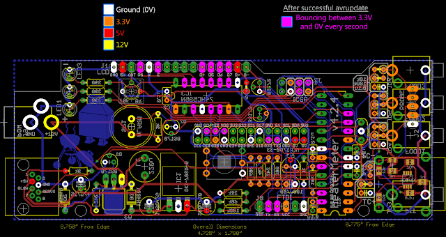
Here is a useful diagram to use to troubleshoot the HM

 
Last edited:
Hey everyone. Great day for smoking. Currently have a brisket, beef and pork ribs, and 2 chickens going. I am using 4 Themaltake probes TX-1001X-OP. They were off a lot so I calibrated them. The 3 food probes were around 80 degrees under the 212 boiling temp of water, and the food probe was 145 degrees over 212. I have all my food probes set to Thermaltake TX-1001X-OP in the settings menu. The offset will only go up 100 degrees over and I need another 45 to be on target. Any thoughts or suggestions? Thanks!
 
Hey everyone. Great day for smoking. Currently have a brisket, beef and pork ribs, and 2 chickens going. I am using 4 Themaltake probes TX-1001X-OP. They were off a lot so I calibrated them. The 3 food probes were around 80 degrees under the 212 boiling temp of water, and the food probe was 145 degrees over 212. I have all my food probes set to Thermaltake TX-1001X-OP in the settings menu. The offset will only go up 100 degrees over and I need another 45 to be on target. Any thoughts or suggestions? Thanks!

This should be in it's own thread as it's not related to the OP's first post. If the TX-1001X-OP probes are off, I'd verify your 10k resistors on the board are reading properly.
 
Sorry. This was the closest topic I could find. I didn't know if I should start a new thread. Thanks. Do you have any suggestions how to check the 10k resistors with a multimeter (plugged in or off, checking ohms or dc power?) Also, this is my first and was wondering if setting the food probes 80 degrees higher as offset was normal. Seams a little high. Thank you.
 
Hi Everyone. I just finished building my first heatermeter 4.2.4. Using an old Sandisk sd card (512 MB). Using the usb to power on the rPi when connected to heatermeter board. I only get blocks in the top row of the LCD. Second row has nothing in it. After 'power on', I see the lights on the rPi blinking. The yellow and green LED on the HM are constantly lit(never see the red one come one, if it is supposed to). I checked my solder joints and thought I over soldered some resistors near the probe ports so I cleaned those up. Still getting the same results. Any ideas? What would the symptoms of a tempermental sd card be? One other thing, I had ordered the amber LCD from Mouser but the LCD isn't amber, not certain if the LCD is part of the issue.

Dave

Dave does the LCD light up amber when you adjust the little blue trimmer?
 
Dave S,
Nope, the LCD doesn't turn amber. Just has black boxes in the top row and the screen itself stays the 'greenish' color it is when there is no power.

Issues I am having (note, in this picture, I don't have the rPi connected but it is the same thing if I did connect the rPi):


Pictures (please go gently on my soldering skills): Now that I look at the board using the pictures, I could see where some solder spots may need touched up. Doing the solder job for a couple hours really messes with the eyes....
Top of board (pic 1)


Top of the board (pic 2)


Bottom of the board (pic 1)


Bottom of the board (pic 2)
 
Steve,
That could be the whole issue, I was afraid if I held the solder 'wand' too long it would start to melt the board. I did look at some videos and they stated it should take about 5 seconds to solder a connection, 3 seconds to heat it up and the other 2 to get the solder to 'melt and run'.

I will watch that link and improve my solder joints to see if that helps.

Once I get some sleep, I will take another shot at cleaning up the solder joints.

On a side note, I did notice that all of the resistors I received from Mouser were blue while Bryan's pic show blue and the 'beige' colored ones.

Dave
 
It seems counter intuitive, but you want the soldering iron to be quite hot so that you can get in and get out pretty quickly. Keeping the iron too low will mean you'll be waiting too long for the heat to melt the solder, which is bad.
 
Yup, I'd resolder the socket where the PRI connects to the HM board, looks like some are bare or not enough.Also redo the atmega socket.
Only way you can hurt the board when soldering, is holding the soldering iron on a pad or part for more than a minute or 2......if you can see a hole where the part comes through the board, hit it with more solder, except the jacks.

When you solder, make sure you touch the part and the little pad at same time to get the solder to flow.
 
Last edited:
Some tips I can give you is make sure the pad is completely covered with solder, also I use sliver bearing solder because it has a lower melting point then most other lead free solders.
 
Last edited:
Success!!!
I did resolder almost all of the connections...it was quite easy using a 'helping hand with magnifying glass' to see the connections and the solder. In addition, the link that Steve_M provided helped, especially with the temp setting. I was going around 200 Celsius, just above the melting point of the solder until I watched the video. Kicked the solder station up to 350 (which may have been a little high for the .032 diameter solder but that helped a lot).
Not certain if the issue was the solder joints but I removed the ATmega328 chip before I did the resolder and noticed it came out very easily. When I put it back in, I made certain it was completely seated.

Now I get this on the amber colored LCD:


Thanks Everyone for your suggestions and helping me with my soldering skills.

Next on the list is the blower connection, setting/verifying the probes and web site interfere (I like the flames that most people use on theirs).

Dave
 
Hey, nice. That's looks considerably better than before. I keep my iron at around 320 C, sometimes a little higher.

Glad it all worked out.


Back
Top