Did I break something on HM?


Tony L-Iowa

TVWBB Fan
I had a working HM that controlled a SSR within my electric smoker. The SSR was mounted inside the smoker and I discovered things were too hot there when the HM shutdown (LCD off) and I discovered that the blower control wires driving the SSR shorted together. I replaced the shorted wires, replaced the SSR (and mounted it in a location outside the smoker. Today I did a quick test to see how things were going to work. I found that the HM appeared to operate and wasn't shutting down and the fan control graph looked like the fan output was variable. But, the SSR controlling the heating element never appeared to kick off when the fan control output went to 0%. Would shorting the fan output wires have damaged some internal parts on the HM? Or should I look for some other variables like the new SSR possibly being bad? Here's a graph (I shut it off at the peak after detecting the overrun):

ObV0Y5W.jpg
 
So bottom line, you shorted out the blower wires (when your SSR failed)....
Do you have a multimeter? If so, measure DC voltage on your blower wires when the HM is blowing at 0% and then again at 100%... It should hit 12V when the blower is supposed to be on. Do this without the SSR connected to eliminate that as a possible issue. If your 12v isnt going on and off with the blower graph then you need to troubleshoot the HM blower drive circuit and find out what died on you...

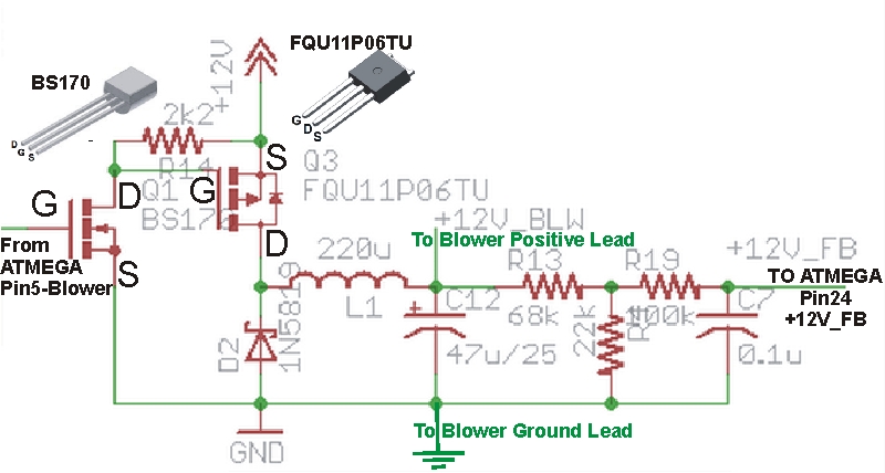
Here is a copy of the HMv4.2 blower circuit with some notes:
HMv4.2_BlowerDriver.jpg


You shorted where it says "TO BLOWER POSITIVE" to ground... So, maybe L1 melted open? It's an inductor, so just check for continuity through it, if it is an open circuit its trashed. Then check the two transistors and the diode....
 
Last edited:
Ok... I pulled open my HM. I see 12VDC when fan output says 0. I don't have a PIT probe(thermocouple) currently plugged in so this should be off and no voltage, correct? checked the inductor with the unit off and it has continuity. How do I check those transistors? power off of HM and check continuity between DS?
 
OK, so your blower seems to be locked ON now I guess, should not have 12VDC when the HM is at 0%...
What mode is your blower set to run under, Pulse or Voltage? If set to voltage try it on Pulse, that would give you a clue if the problem is in the feedback circuit (if 12V goes on and off in Pulse Mode) or the drive circuit.
Diodes should read like open circuits (very high resistance) in one direction and near short circuit (very low resistance) in the other direction (when out of circuit). If they appear open both ways or shorted both ways (out of circuit) the diode is bad. You could have popped the MOSFET Q3, with the power off is the D leg shorted to the S or G leg?

I use pulse mode. If the picture you posted in correct I do see continuity between D and S on Q3. On the diode nearest Q3 it's open both ways (in circuit) when I use my fluke 26III multimeter diode testing mode. When I check the diode nearest the CAT5 reads (in circuit) open in one direction and ~240 ohms in the other. I assume this is a good diode. So, do you think my Q3 and the diode next to it are both bad?

Suggestions on parts to order from mouser? Looks like I have to pay $5 shipping so I want to make sure and get everything it could possibly be. I currently put a few of the Q3's and the Q1's on the order as well as a few of the 1n4001 diodes. Before I place the order I want an opinion on any other stuff I may want to add to that cart (if any).
 
Last edited:
Between D and S on the MOSFET Q3, with your meter in diode mode it should read like a diode... Open in one direction and beep like a diode in the other... Not full on continuity in both directions like a short circuit. D2 should also read the same, open in one direction and about .5VDC in the other (with meter set in diode mode).
 
As for what parts to order, all the parts to the left of the "Blower Positive" location wouldn't cost much to order, that said, it seems L1 and/or Q3 would be the most likely parts to fail.
 
Thanks Ralph,
I ordered a few spare Q3's, Q1's, L1's, and 1N4001's. I'll replace Q3 and the diode I think I was having issues with first and see how it goes. Probably be a week before I get the parts. Luckily I had a 2nd HM I built and was able to use as a backup for my salmon smoke today.
 
1N4001 was not reading right in circuit.

Thats kinda odd, cause the 12V for the blower circuit breaks off before the 1N4001, so the current for the blower doesn't pass through the 1N4001, just the 5V and 3.3V current goes through that diode. The other diode (1N5819) is smack in the middle of the blower circuit, so if any of them failed due to shorting the blower leads I would suspect the 1N5819. That said, grounding the blower positive lead essentially eliminates the 1N5819 from the circuit as well as the rest of the blower feedback components, so less current (none) should be flowing there because current will take the path of least resistance which is the dead short ground on the blower positive lead. With the blower positive grounded current will whip right from the 12V source through Q3 and L1 to ground. Since Q3 appears to be stuck ON I kinda assume it is what has failed, though Q1's job is turning Q3 on and off, so it could be the culprit too but it's not in the direct path of the current flow like Q3.

If you measure DC voltage on Q3 with no load (no blower attached) the readings will look kinda funky, the output will shoot up to the PS voltage (12VDC or whatever voltage your PS is putting out, usually quite a bit higher with no load). If you apply a load (blower) you should see the center pin of Q3 go from 0VDC up to something near 12V as the HM goes from 0-100%. The center leg of Q1 should go from 0VDC to about 1.5VDC when you sweep the HM from 0-100% (with a load attached), with no load it will read funky too...
 
Ralph-

I finally got around to replacing Q3 tonight. It was definitely bad when I tested it. I retested 1N4001 and didn't see an issue (not sure what I was doing last time I measured it). So, I guess I'll do a test run with the fix soon. That Q3 is a bear to replace if anyone puts any solder under the heat sink. I had a little there and it pulled up the pad a little
 
Yep, Q3 fixed it. Did a short run up to make sure it wasn't going to stay on. I had to resolder a broken ribbon cable wire to my LCD also since it broke sometime during my repair job.
 
Glad replacing Q3 fixed it up for you... That seemed like the moist obvious point of failure knowing what happened....


Back
Top