Michael Pitra
New member
Hello. First of all, I want to thank the whole community for supporting this great project. I've ordert all parts including the PCBs and soldered everything, including LCD. Powering the RPi works, the SD card boots up. I can connect to my home WiFi network correctly and see the web pages.
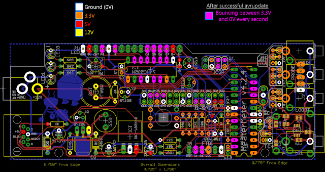
But when the HM board is connected, the communication doesn't work correctly - it seems that the serial communication to the ATmega is not working as expected. In the log I can see that the "avrupdate" command failed. Trying it by hand (from the Configuration screens, using the hm.hex file) doesn't work as well. LCD seems to display the top line with blocks, so the shift register and the LCD components seem to function properly.
When powering on, the LED2 and LED3 light up for a short time, so this seems to be ok too. The LED1 does nothing at this time.
The funny thing: I tried some measuring with the multi meter while powered on, and when connecting GND to the 3rd pin of the ATmega (counted from top, left row), the buzzer seem to make some noise. Connecting to the 4th and 5th pin is even weirder: the LCD backlight starts to light up, sometimes it comes to flashing with long intervals, sometimes with long intervals. After playing around with pin 4 and 5 some more, suddenly the "No Pit probe" text line appeared on the LCD. So I thought, the "avrupdate" command worked in the background, and looked on the web pages again: still no communication to the ATmega. Sometimes also all LEDs startet to light up. Somehow everything is working, maybe there's a bad soldered item somewhere, but I can't figure out where to look first.
Can you help me? If there's a need for pictures of my soldered work, just tell me.