Bryan Mayland
TVWBB Hall of Fame
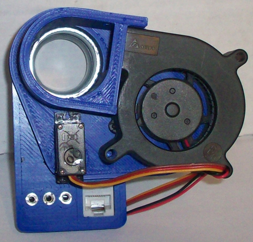
My printer seems to be behaving itself again, so I was able to finish printing an Adapt-a-Damper. I created a tunnel piece as well to hold an anemometer for air flow testing. I made the tunnel longer because the blower actually generates a magnetic field that triggers the hall sensors in the anemometer and creates false readings. The output of the tunnel is 881mm^2 and the input is 845mm^2. The HeaterMeter was set to 225F and the temperature allowed to stabilize before switching to manual mode.

The first test I did was with the standard configuration, Blower and Servo are directly linked to PID output and run from 0% to 100% across the board. At the initial 5%, there's a big bump up, but after that, there's a relatively straight line up to maximum output.

I then tried to do Servo Ceiling 50% + Fan floor 50%. That is, run the servo up to PID 50% at which point it will be fully open, then turn the blower on at 51% where it will be on at 2% all the way up to 100% at PID 100%. Unfortunately, the anemometer can't go below 2.5 kph without stalling out, and the convection airflow was not enough to reach 2.5 kph so everything from 0% to 50% read as 0%. As soon as the blower kicked in, it would register at 10.6 kph. I decided to switch to using a mass airflow sensor instead.

The mass airflow sensor heats a PTC and records how much current it takes to keep the PTC at that temperature (looks to be around 58C) and the current required is proportional to the air flowing across the PTC. This is sensitive enough to tell I am breathing out of my mouth from a couple feet away. I fitted the sensor to my tunnel and reran the two tests. The units here (air mass) are different from the first set of tests (wind speed).


Around PID 20% (damper 40%), the convection airflow levels out so effectively PID 20%->50% are the same output. Then at 51% BAM huge spike up. Watching the HeaterMeter try to control this is fun because 50% isn't enough to maintain 225F but 51% is way too much. Comparatively, a fully open damper with the fan off allows less airflow than a fully closed damper with the fan running at 1%. Changing the Max Fan Speed does nothing because 1% blower output is the low end-- changing the top end has no effect.
It is almost like we could use a mode where the servo goes PID 0% -> X% then at X% the damper closes completely and the blower kicks in, and the two ramp up together after that. The disadvantage to that would be that as it crosses that point the servo will go from 100% to 0% so going back and forth across that boundary the servo will look like a crazy person, and the large difference between no blower (~0.6) and closed but with the blower (~2.1) is a large enough step up that it is very possible it would just wobble from one side of the threshold to the other.

The first test I did was with the standard configuration, Blower and Servo are directly linked to PID output and run from 0% to 100% across the board. At the initial 5%, there's a big bump up, but after that, there's a relatively straight line up to maximum output.

I then tried to do Servo Ceiling 50% + Fan floor 50%. That is, run the servo up to PID 50% at which point it will be fully open, then turn the blower on at 51% where it will be on at 2% all the way up to 100% at PID 100%. Unfortunately, the anemometer can't go below 2.5 kph without stalling out, and the convection airflow was not enough to reach 2.5 kph so everything from 0% to 50% read as 0%. As soon as the blower kicked in, it would register at 10.6 kph. I decided to switch to using a mass airflow sensor instead.

The mass airflow sensor heats a PTC and records how much current it takes to keep the PTC at that temperature (looks to be around 58C) and the current required is proportional to the air flowing across the PTC. This is sensitive enough to tell I am breathing out of my mouth from a couple feet away. I fitted the sensor to my tunnel and reran the two tests. The units here (air mass) are different from the first set of tests (wind speed).


Around PID 20% (damper 40%), the convection airflow levels out so effectively PID 20%->50% are the same output. Then at 51% BAM huge spike up. Watching the HeaterMeter try to control this is fun because 50% isn't enough to maintain 225F but 51% is way too much. Comparatively, a fully open damper with the fan off allows less airflow than a fully closed damper with the fan running at 1%. Changing the Max Fan Speed does nothing because 1% blower output is the low end-- changing the top end has no effect.
It is almost like we could use a mode where the servo goes PID 0% -> X% then at X% the damper closes completely and the blower kicks in, and the two ramp up together after that. The disadvantage to that would be that as it crosses that point the servo will go from 100% to 0% so going back and forth across that boundary the servo will look like a crazy person, and the large difference between no blower (~0.6) and closed but with the blower (~2.1) is a large enough step up that it is very possible it would just wobble from one side of the threshold to the other.


