2nd Build - Fan running 100%


Greg Fountaine

TVWBB Member
On my first HM build I encountered this - I had the fan wired incorrectly to the 5v lead :)

I'm using the fan that works on my 1st HM just fine -
On the new build it runs 100% all the time - I tried turning it off hitting the left button to for lid open and it kept cruising at 100%


Any ideas on where to start on that?

Thanks!
Greg
 
On Q1:
the leg that's supposed to be 0/3.3V, at 100% it's 2.3V, the leg that's supposed to be 0/12V is registering 2.3V @ 100%
At 0%, the 0/3.3V leg is 0V, the 0/12V leg is 7.2V

Need a hand on where to look next :)
 
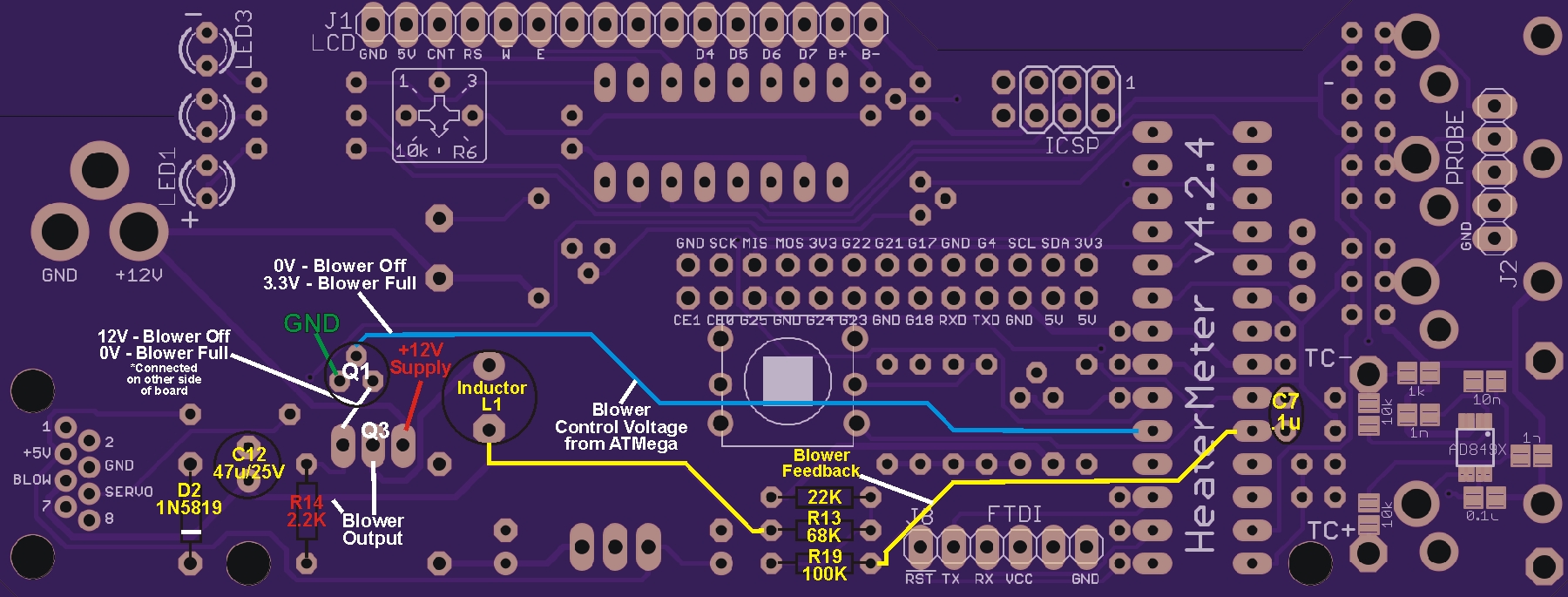
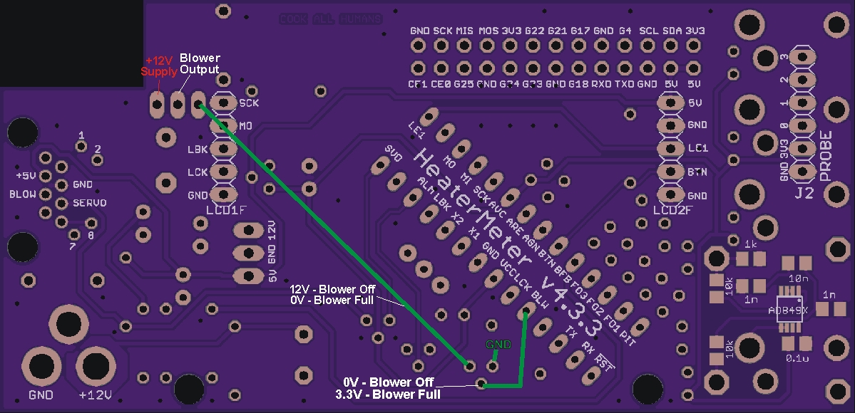
I would look for solder bridges on Q1 and Q3, and make sure you have the right part in Q1 position. Here is a diagram that shows the voltages at various points in the blower circuit when the fan is at 0% and 100%. The more complete diagram shows the HMv4.2, 4.3 is also shown with less detail. The circuit is the same but part locations are different.
In ether case, the center pin on Q1 should go from 0-3.3v when going from off to full. If not you can remove the ATMEga, bend pin5 out a bit and reinstall the chip so pin5 does not go into the socket, then measure Pin5 to see if it sweeps from 0-3.3V properly? If so then the logic is working and you have a problem in the blower circuitry.
*Also check R14, if that is not making a complete circuit the transistors will not be biased properly.

HM_Blower_Notes.jpg


HM_Blower_Notes_V4.3.jpg
 
the bent out Leg 5 on the ATmega is running 2.3V @ 100%, 1.15V@50%

Did not see any solder bridges on Q1 or Q3

I'm not sure what I'm supposed to check on R14, it is the correct resistor and it's solder joints are ok from what I can tell.
 
What are your fan settings? Set min=0 max=100, startup max=100, on above 0% and redo the test. Pin5 should go from 0V to 3.3v with these settings.
You didnt report what Pin 5 reads at 0%? That is the critical reading as your issue is the fan wont turn off. It should be 0v, if not then you have an issue on the logic side of things.
 
Set min=0 max=100, startup max=100, on above 0%
I had max=70%, :(

it reads 0V at 0%, 3.28V @ 100%

Thanks for the help Ralph - what's next? :)
 
So that confirms logic is working properly, you can reinstall PIN 5 of the Atmega now...
Next, in the config set the blower to PULSE MODE for now, this eliminates the feedback circuit. Does your blower work properly now? What voltage are you reading on the center pin of Q1 at 0% and 100%? Look at the diagram(s) above, set the HM to 0% then 100% and take voltage readings looking for 0V/3.3v and 12V/0V respectively. What do you see voltage wise in those two spots?

EDIT: I'm assuming since you improperly wired the blower to the 5V lead on your first build you didn't do that again?... but you might check continuity (with the power off) from the + wire you are using for your blower to the BLOW pin on the HM, just to make sure you're wired up properly.
 
Last edited:
Q1
In voltage mode: on the 0/12V leg I'm only getting 7.6V @ 0%, it goes to 6.6V @ 100%
In pulse mode, it's 7.5V @ 0% and 0V @ 100%
In pulse mode the 0/3.3V leg, 3.3V @ 100%, 0V @ 0%
And the fan still runs 100% either way

I did check continuity as a sanity check on the BLOW pin and the lead to the fan, that's good.
 
Last edited:
Forget voltage mode for now, it will just confuse things, readings in voltage mode are more difficult to interpret anyways....

In pulse mode what do you read on the center pin of Q1 at 0% and 100%?... and on the output side (where the green line is on the board diagram)

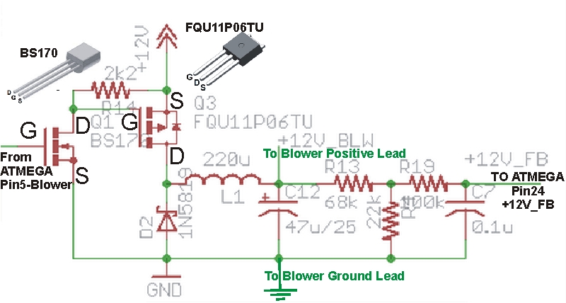
Here is the blower schematic:

HMv4.2_BlowerDriver.jpg


Everything to the right of the blower positive lead is the feedback circuit, needed for voltage mode only.

R14 is where the 12V enters the picture, check its value and check continuity to both transistors (in all spots). One time I had this issue and R14 was only making part of the circuit...
 
at 0% fan, got just over 12V on oneside of R14, 7.8V on the other.

D2 is a Diode - it's in right (both diodes are correct polarity), C12 is a capacitor?
 
Yes, C12 is an electrolytic capacitor, one of the "cans". It has polarity marked on the side, usually a stripe on the side with the negative terminal,
 
I checked a couple of things for continuity -
There is NOT continuity between the BLOW pin and the 5V pin on the solder side.

Also I checked various ground points for continuity to the GND lug on the power for the HM.
I found continuity to Q1 and Q2 but NOT to Q5 for the pin on the right looking at the solder side of the board.
Which it doesn't appear that leg goes to ground looking at the traces, but, thought I'd point that out.
 
You've got something shorting the gate of the MOSFET (the right-most pin looking from the top) to something else. I'd disconnect power and just check continuity to everything else. It should only show as being connected to the closest pin of the 2.2k resistor and the closest pin of Q1. You can check all the connections though, I've made this chart of what is connected to what:
Code:
TEST 1 2 3 4 5 6 7 8 9
 1   1 2         7
 2   1 2         7
 3       3   5     8
 4         4   6
 5       3   5     8
 6         4   6
 7   1 2         7
 8       3   5     8
 9


I've only indicated where you should see a connection. Put one probe on "1" and then test 1-9 and you should get a beep at 1, 2 and 7, and nothing at the others. Then put the first probe on "2" and test 1-9 again, and so on down the list. Note that in the image, the number 9 is on two spots and nothing you test should ever be connected to it.


Back
Top