Magic Smoke


Darren C.

TVWBB Pro
I was trying to figure out why my servo wasn't moving (could just be my config as I don't quite get the servo part of that yet) and I shorted something. With the HM running, I was using my multimeter on the plug on the damper end of the ethernet cable. I'm using the MicroDamper with the plug. I think I got my multimeter probe crossed on the plug and shorted out the fan circuit. I got the dreaded smoke. I can boot the HM with the thermocouple probe in; the LCD displays the current temp and everything seems to function as normal, until the fan kicks on. Then, the smoke starts back, it beeps and I think it's rebooting. I've visually inspected everything as closely as I can. There seems to be an area around the MOSFET 60V P-Channel QFET on Q3 that looks darker than I think I caused by soldering, especially around the center probe. So, does this seem like a likely suspect per my description? I've got to place an order to Mouser. So, tossing in an extra one is no problem. Any suggestions?
 
Last edited:
You want to look at Q1 and Q3, one or both is likely toast. You may also have damaged the inductor or D2, r14 etc.
Here is the schematic diagram of the blower circuit so you can see the parts involved here.
HMv4.2_BlowerDriver.jpg
 
Thank you so much for the pointers. I'm not good enough with electronics to make complete sense of all you said. But, at the very least, I can use your listed parts a parts list for Mouser. But, I am going to try and decipher the schematic. I'd like to learn a little. I bought a new multimeter yesterday that has a diode setting. I put the probes across D2 and D3 (wasn't sure which was which) and got something like .175 one way and nothing the other on both diodes. So, I think that means they are good, no? R14 seemed to have exactly 2.2k of resistance. So, I believe that is good as well. I googled how to test the inductor. I am ignorant on this as I have never had a digital multimeter and never checked components on this level. But, I set the multimeter at 200 ohms and got about .3 across the inductor. I don't know if that is good or bad but I read they have little resistance. I have no idea how to check Q1 and Q3. I will google that as well and see what I can come up with.
 
Last edited:
You are doing great, low resistance one way and high the other is good for diodes. The inductor is the hardest part to test, you really need to do a "ring" test which cheaper meters wont do. IDK the expected resistance value on the wire in the inductor itself but that may not be a good indicator of the health of the inductor anyway.
In general the transistors should measure like a pair of diodes between the three pins, if you've got legs that seem shorted in both directions that is probably your bad part.
If you need to order parts I would probably order a new inductor as well, I would probably order c12 and everything to the left because the parts are gonna be really cheap (compared to the shipping). Why save nickles and dimes and end up shipping twice...
 
Thanks. This is the meter I bought. I kinda just grabbed one. It had more options on the dial so I figured it would give me more control. I could still exchange if if you think I should. But, most of my experience with meters is just checking continuity and voltage. So, something too professional would be a waste for me.
 
I dont see capacitor or inductor tests on the meter, and you'd have to remove them from the board to test accurately, if you're not deep into electronics that meter should be fine. If you look at the schematic, the blower connects right after the inductor at the top of C12, so any current through the blower wire has to pass through the inductor. If you drew enough current to pop the mosfet that might be enough to melt windings in the inductor, so my advice is just replace the inductor with the transistor, or at least buy the spare inductor if you are ordering parts. If the inductor is damaged from my experience the blower wont work properly in Voltage mode, it will be more on/off rather than ramping speed properly.
 
Okay. This looks like C12 and left to me. I broke a BS170 yesterday and needed an extra one of those. Plus, I more or less doubled what I thought I needed. Does this look like it will cover the blower circuit? I now this is kinda a stupid question, probably unanswerable, but while I'm ordering, are there any additional parts that might impact servo operation that seems like low hanging fruit to order? I don't know that I have a problem with it. It might just be my understanding of configuration settings. But, that's what led to the magic smoke.
 
This is interesting. I just reassembled everything and put back in the case for safe keeping until parts arrived. I plugged it in, because that didn't seem to cause any harm before. I like watching the ambient temp from the pit probe. I rolled the dice and put it in manual fan mode. I don't have anything plugged into the RJ45. But, it appears to be functioning properly. The LCD indicates the percentage and so does the web gui. I'm starting to wonder if the RJ45 has a short.
 
I just removed it from the case and put the fan through different percentages while testing voltage. With the multimeter in voltage mode and the ground probe on the gnd solder point of the RJ45, I got 4.96v at the +5v solder point and almost 21v at the blower solder point, regardless of percentage. The fan output is in voltage mode.

That seems like too many volts to me. Everything I've been seeing in the documentation is either 5 or 12v. Does this help identify the problem?
 
The voltage on the blower pin of the CAT5 jack can't be larger than the supply voltage, what does the output voltage of your power supply read?
 
as for other parts re: servo, there is one BS170 between the ATMega and the servo, so get a spare BS170. They're cheap enough to have spares...
 
Well, the PS is rated at 16VDC, not 12... And apparently it is running high!
The only things that use the 12V are the OKI regulator and the blower, the OKI is good to 36V input so that's not a problem. The FQU should be alright with 21v but I'm not sure about the BS170 or the blower itself. My advice is try a 12V power supply
 
Okay. I found an 18v and a 10v. So, I went with the 10v. I suppose that will prevent the fan from running at its highest level, I don't see where that's going to be a big deal. The BS170's are cheap so I planned on ordering extra. Did you think the Mouser parts list that I linked to looked okay? I really don't know if I have a servo problem or if I just haven't gotten the configs set correctly. I hate to place two separate orders. Are there any servo parts that I can throw in the cart that might cover me?
 
As I said before, there is one BS170 between the ATMEga and the servo, that's it... well, there is one 1K resistor as well but it is highly unlikely it is damaged.
I guess the HM should run on 10V, as you said, the blower won't hit full speed. Just make sure it is TIP POSITIVE.
 
Yeah that power supply is bonkers. At 16V HeaterMeter should pull enough power to keep a decent supply in regulation and 20.4V is way out of spec! Seeing 20V on the output is normal as well with no blower attached because HeaterMeter can't lower the voltage if nothing is attached (the capacitor there holds the charge). All of the components along the blower output path are fine for that voltage but watch what we have here in order of decreasing tolerance:
Resistors 250V
BS170 60V
Power MOSFET (FQU) 60V
1N5819 40V
5V Regulator 35V
12V Input cap 25V
Blower output cap 25V
Blower 13.8V

Did you have your blower plugged in when testing? When the blower first kicks on, HeaterMeter pushes a dead short from the power supply to the blower for a short amount of time to get it spinning. If the power supply is putting out 20.4V then it is a good chance that it killed your fan. Test the leads on the blower with the multimeter set to ohms (200) and make sure they aren't reading as being connected, they should show as being completely isolated. If it is reading something then that could be your problem, if it is reading a short, then that is definitely a problem.

I've previously tested up to 14V with a blower attached with no problems, and up to 20V with no blower attached. I just did a quick test of 16V. It worked but the blower made a upset noise for an instant before it started spinning, but then HeaterMeter kept good regulation. At 20V the fan made a quick tick, the servo spazzed out, and everything rebooted. Seems like 20V is too far out of spec for the blower to deal with and it starts to cause issues. My blower and everything still appear to work though.

You can also test with your 10V supply and a computer fan (or any other 12V fan you have on hand) to see if your HeaterMeter will still run it without smoking.
 
@Bryan
I didn't have time to digest your comments and test it completely this morning before work. I did try checking continuity at 200ohms on the fan leads. I got a reading, can't recall the reading atm (I was hurrying). And, I tried plugging the cat5 back into the jack to see if I'd get smoke. I didn't get smoke, but I got a beep and a reboot. I left it plugged in just to see if would heat up. I ran the fan percent up in manual mode to 35% and never got the fan to move. So, I think the fan might be toast. I do believe I'm pushing 100% of the voltage through the fan circuit at everything over 0% output. I didn't have time to verify that this morning. But, I think that was the result I was getting yesterday, IIRC.

If I understand your question correctly with regard to the fan being plugged in during testing, the answer is "no". When I was originally troubleshooting the servo, before the smoke, the fan was not plugged in. I think I just accidentally shorted something with my multimeter probes.

I'll look at everything closer and try to follow your comments better when I get home this evening.

Just a quick question for clarification, are you suggesting that with the blower being 13.8v, it makes it the weakest link in the blower circuit and the most likely to fail? If it wasn't connected at the time, then I'd move up in the list of parts?
 
The blower seemed like the most likely issue, because pushing 20V through it is well beyond its capacity. But if it wasn't plugged in at the time, then it should be ok. You can test the blower itself just jamming the red wire into your 10V power supply (inside the barrel hole) and touching the black wire to the outside of the barrel and it should turn on.

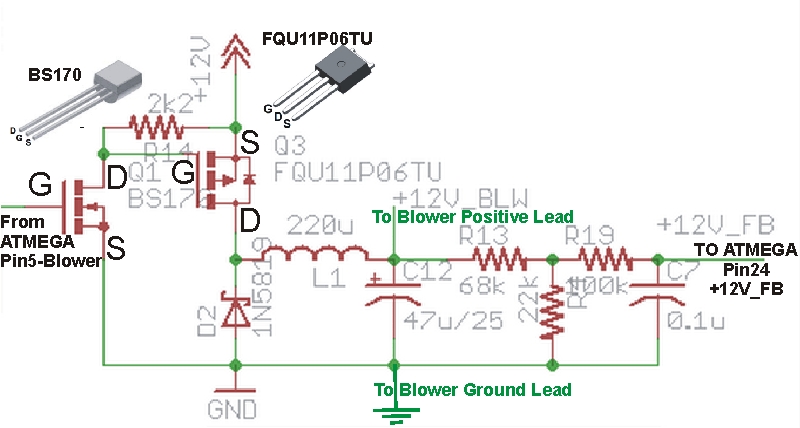
Everything else I can't imagine how it would break. The inductor is good for 1A continuous. The BS170 is on the low voltage side really and doesn't pass any current. The 47uF/25V capacitor is likely good because those tend to blow out and leave blackness either on their tops or bottoms, and the blower would still run even without it. The power MOSFET is rated for 9.1A and your brick could only put out 0.9A. It should be good for any instantaneous short, however if you shorted it for a long time then eventually the power MOSFET will overheat because it is dropping ~16W.

I figured why not stop speculating and just blow out a HeaterMeter here. Set the power supply to 16V 1A and shorted the fan leads together and waited to see what went first.


If your leads stayed shorted for more than 10-15 seconds, it is very likely that the only thing damaged was this power MOSFET (the FQU one) which should never be this hot. I would suggest removing it then make sure the you still have continuity between the center unpopulated MOSFET pin hole and the BLOW pin at the RJ45, and also from the left pin hole (with the Boxy robot logo facing up) to the pin labeled 12V at the barrel jack. We just want to make sure your traces are still intact, which would be crazy if they were. Those two check out, I'll send you a new FQU and you'll be back in business I believe.

To remove the MOSFET, just clip the legs off on the component side so the part falls away, then heat one leg at a time until the solder is liquid then smack the board against the table to knock the solder and leg free. If you have access to solder wick that would be easier probably.

For reference, in normal operation, the 2.2k resistor is the hottest component around at 10C above ambient. With a 16V power supply, the MOSFET becomes the hottest at about 25C above ambient. Not that I am in any way suggesting anyone should use a 16V supply due to the problem that the blower would get angry.


Back
Top