Version 2 of my homebrew controller


right on!

which locking connectors did you decide on s roy? i plan on using anderson powerpoles for the power in & im using a rca connector for the blower.

have you fab'd a mount yet?
-sj
 
I am using switchcraft DC Power Connectors Pwr Plug Sealed IP68 2.5mm from mouser (761KS12). I will use this on power in and out. I have not decided on how I will mount it yet.
 
Guys I am sorry that I sent you off on a wild goose chase in regards to the modified Asynclabs files!

I need to document them on my site, and I will probably also just post the entire modified library as well.

Thanks for making it painfully obvious that I need to do this
icon_eek.gif
 
Thanks Bob, this will help anybody else who want to take on this project to get up and running quickly. Once again thanks for all your help.
 
I also had problems with the radio shack plugs, I got them to work but only really b/c I have a small washer underneath them that backs them off the 2mm needed.

Mounted mine in a standard radioshack project box, nothing special, but it all seems to work for me:

http://www.bbqbuds.com/josthei...oto_manager/albums/1

Once tactical mistake I made was putting an on/off switch on the bottom of the box instead of the side, so my box has to lie on its back.

James
 
Originally posted by j ostheim:
Bob-

I'd recommend uploading the projects to http://www.github.com, so that people can fork the software and use it in a version controlled manner.

I'll be happy to do it once you put all the files on your site.

James

James - you have a comma in your link url. Interesting site!

Curt
 
Actually this forum software added the comma, lets just say I am not surprised...

James

Originally posted by Curt Timmerman:
<BLOCKQUOTE class="ip-ubbcode-quote"><div class="ip-ubbcode-quote-title">quote:</div><div class="ip-ubbcode-quote-content">Originally posted by j ostheim:
Bob-

I'd recommend uploading the projects to http://www.github.com, so that people can fork the software and use it in a version controlled manner.

I'll be happy to do it once you put all the files on your site.

James

James - you have a comma in your link url. Interesting site!

Curt </div></BLOCKQUOTE>
 
Finally finished up mounting it in the project box. It is up and running. Now all I have to figure out is how I am going to mount the Blower.
 
My turn to thank all of you for the idea of making my own controller and I'm currently fumbling through my own implementation. My addition to the build is a pot connected to one of the analog input pins for setting the thermostat.

I have some questions for you: how many of you had to fiddle with the fan algorithm? I'll probably end up with a different fan/blower than Bob's original plan so I'm wondering what changes some of you made.

How responsive is the temperature once the controller changes the fan speed? A couple of minutes?
 
Yes, it is 5cfm. I also ordered a 10cfm fan the same style. There should be no need to mess with the code for the fan. It should run any 12vdc fan right out of the box.
 
Bob, I'm new to this thread and I was reading your posted where you stated you attached the datasheet for the ET-73 Thermistors. I couldn't find the datasheet anywhere. Could you email me a copy. I'm working on a project using these same probes.

Thanks,
Bobb
 
I had a chance to get back to my version of this project this weekend. I've been gone for a while because I apparently decided I had too much money and would enjoy buying a house and then giving most my income to Lowe's.

Anyway, the button inputs area isn't right yet, but I built the rest of this schematic for a 2 FOOD, 1 PIT, 1 FAN, 1 AMBIENT sensor controller based on Bob's design.

I designed this board layout which measures 2.2"x1.1". I would have preferred to use pin headers to hook everything up, but since I didn't have any on hand, I just soldered everything directly into the board. That board layout proved to be a little overly ambitious considering I left no room to solder stuff together. It could possibly work as a PCB layout, but my implementation ended up closer to 2.1"x1.4".
Ratsnest Image
In action Format is Sensor letter / Raw ADC value / Temperature in F. Sensor D is a 10k thermistor soldered to the board.

I've also built a mockup fan housing from this design. It has a few flaws I would have fixed this morning in the CAD, but the CAD program (HeeksCAD) has decided that it doesn't want to load the file properly so I'm going to redo it in Google SketchUp.

For the record, I used DigiKey Part #CP-2508-ND CONN AUDIO JACK 2.5MM MONO for my Maverick probe jacks and they fit perfectly. My only gripe with them is the short collar which is going to make mounting them in my project box a little challenging (the shaft is only 2.9mm and my project box thickness is ~2.5mm).
 
[/QUOTE]For the record, I used DigiKey Part #CP-2508-ND CONN AUDIO JACK 2.5MM MONO for my Maverick probe jacks and they fit perfectly. My only gripe with them is the short collar which is going to make mounting them in my project box a little challenging (the shaft is only 2.9mm and my project box thickness is ~2.5mm).[/QUOTE]

I used the same jacks they work awesome but were a pain in the butt to mount due to their size. and short collar. I was able to make it work.
 
bryan, i like your ambient temp idea! i have some thermistors laying around doing nothing.

you may want to check out fritzing for easy pcb layouts.

i picked up some large 16x2 parallel LCDs from a guy on another forum and found a whole bunch of 74LS164N shift registers my dad had laying around. the shift register works great if you don't mind the extra soldering. i'm currently using the shift register & lcd combo on another project with excellent results outdoors. i'll be switching out lcds in the smoker controller soon and possibly etching my own board once i settle on a hardware configuration. cheers!
-jfc
 
Oh just wait! I've built this nice little menu system that allows the status screens to rotate like:
Pit:225F [25%]
Pit Probe2 220F
to
Pit:225F [25%]
Food Probe 150F
to
Pit:225F [25%]
Ambient 86F
Press the Up or Down to scroll through these without waiting for the timeout.

You hit the Left/Back button and it puts you into "lid mode" which changes the fan percent to a countdown timer to control resumes (lid mode is also activated automatically when an at-temperature probe drops by a configurable amount).

Hit the Menu button and you can edit the set point, per-probe temperature offsets and names, lid timer and offset. Although I wouldn't want to set the probe names via this interface because it is the whole upupupupupupupupupupupupupupupupup enter upupupupupupupupupup enter etc.

I need to work on my web pages though. They look horribly uninteresting like it is 1998 or something. I am also down to under 4k left with only one web URL so I might have to consider cutting some things out soon.
 
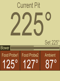
Here's sort of what I was thinking about for the web interface. The color will most likely change, but the layout will be pretty much like this
mockup-v1.png


Clicking the text pit temperature or setpoint will somehow prompt to change the setpoint. And clicking the probe boxes will likewise allow you to change their names or calibration offsets. The blower bar center is the instantaneous reading and the back bar is the moving average.

I'd like to somehow incorporate the last min and max temperature range, and maybe at some point add an SVG graph? I dunno.


Back
Top