Fernando Tome
New member
Hi Everybody,
After being introduced to the wonderful Heatermeater by a friend and having read all the GitHub articles and watched all of bryan's videos I decided to start on a build myself.
My Friend had ordered sone PCB's and gave me a LCD and Baseboard PCB.
I lent my friend my soldering blower for the SMD stuff and we ordered the parts in the BOM list from Mouser and started the build.
I first waited for my friend's build as he has much more experience in soldering and when his build was successful I stared mine with is tips.
Everything went wonderfully and the first test were fantastic. All buttons worked With the settings set to manually I could control the adap-a-damper and leds worked as supposed.
The web interface worked fine also and since I had to wait for my ThermoCouple I set the HeatedMeater aside.
A couple of days ago I finally received the ThermoCouple and on first test I got a No Pit Probe found.
OK no panic I remembered there was a setting I had to do in the interface to adjust it to Thermocouple, but no luck.
I tried the Shorting of the thermocouple with a breadboard wire, but still the no pit probe message.
Then I tried several of the firmwares, At first I thought I had solved as the new firmware showed 32 degrees on screen, but soon I came to the conclusion this was wrong as I removed the pit probe it did not change etc. Also with the latest firmware I got the message no AVR found.
Back to the latest stable firmware which runs fine and I can even see the AVR reboot if I do a reboot form the web interface, but no Pit Probe.
Back to the forum reading up on similar cases and went though all the soldering with my friend but we can't find anything obvious.
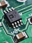
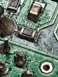
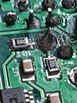
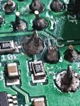
Today I tried to measure all the paths with my multimeter but (as far as I Can measure it) all paths of the thermocouple amp which I suspect seem to conduct and I can't find any obvious soldering bridges.
So I am kind of stuck and Hope someone can give me a clue on where to look next.
I also looked into the ATmega but as everything else seems to be working fine I suspect we can rule that out as the culprit.
Also did a raw data export which looks like this:
API key updatedUser root setting 17 values...
pn1 to Probe 1 = OK
al to -40,-200,-40,-200,-40,-200,-40,-200 = OK
pn0 to Probe 0 = OK
pidp to 4 = OK
pc2 to 7.3431401e-4,2.1574370e-4,9.5156860e-8,10000,1 = OK
sp to 225 = OK
pc1 to 7.3431401e-4,2.1574370e-4,9.5156860e-8,10000,1 = OK
pidd to 5 = OK
ld to 6,240 = OK
lb to 50,255,13,10,11 = OK
pidi to 0.02 = OK
po to 0,0,0,0 = OK
pc0 to 7.3431401e-4,2.1574370e-4,9.5156860e-8,5,3 = OK
pn2 to Probe 2 = OK
fn to 0,100,100,200,16,100,0,100 = OK
pn3 to Probe 3 = OK
pc3 to 7.3431401e-4,2.1574370e-4,9.5156860e-8,10000,1 = OK
Done!
I Have allot of pictures of the soldering but don't want to spam the forum on before hand so wil post as hopefully someone wants to inspect something and asks for it.
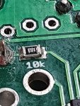
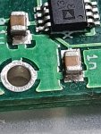
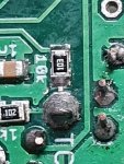
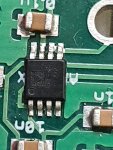
The only pictures I am posting for now are of the SMD soldering.
Please let me know what you think.
Thank you advance!
Fernando
After being introduced to the wonderful Heatermeater by a friend and having read all the GitHub articles and watched all of bryan's videos I decided to start on a build myself.
My Friend had ordered sone PCB's and gave me a LCD and Baseboard PCB.
I lent my friend my soldering blower for the SMD stuff and we ordered the parts in the BOM list from Mouser and started the build.
I first waited for my friend's build as he has much more experience in soldering and when his build was successful I stared mine with is tips.
Everything went wonderfully and the first test were fantastic. All buttons worked With the settings set to manually I could control the adap-a-damper and leds worked as supposed.
The web interface worked fine also and since I had to wait for my ThermoCouple I set the HeatedMeater aside.
A couple of days ago I finally received the ThermoCouple and on first test I got a No Pit Probe found.
OK no panic I remembered there was a setting I had to do in the interface to adjust it to Thermocouple, but no luck.
I tried the Shorting of the thermocouple with a breadboard wire, but still the no pit probe message.
Then I tried several of the firmwares, At first I thought I had solved as the new firmware showed 32 degrees on screen, but soon I came to the conclusion this was wrong as I removed the pit probe it did not change etc. Also with the latest firmware I got the message no AVR found.
Back to the latest stable firmware which runs fine and I can even see the AVR reboot if I do a reboot form the web interface, but no Pit Probe.
Back to the forum reading up on similar cases and went though all the soldering with my friend but we can't find anything obvious.
Today I tried to measure all the paths with my multimeter but (as far as I Can measure it) all paths of the thermocouple amp which I suspect seem to conduct and I can't find any obvious soldering bridges.
So I am kind of stuck and Hope someone can give me a clue on where to look next.
I also looked into the ATmega but as everything else seems to be working fine I suspect we can rule that out as the culprit.
Also did a raw data export which looks like this:
API key updatedUser root setting 17 values...
pn1 to Probe 1 = OK
al to -40,-200,-40,-200,-40,-200,-40,-200 = OK
pn0 to Probe 0 = OK
pidp to 4 = OK
pc2 to 7.3431401e-4,2.1574370e-4,9.5156860e-8,10000,1 = OK
sp to 225 = OK
pc1 to 7.3431401e-4,2.1574370e-4,9.5156860e-8,10000,1 = OK
pidd to 5 = OK
ld to 6,240 = OK
lb to 50,255,13,10,11 = OK
pidi to 0.02 = OK
po to 0,0,0,0 = OK
pc0 to 7.3431401e-4,2.1574370e-4,9.5156860e-8,5,3 = OK
pn2 to Probe 2 = OK
fn to 0,100,100,200,16,100,0,100 = OK
pn3 to Probe 3 = OK
pc3 to 7.3431401e-4,2.1574370e-4,9.5156860e-8,10000,1 = OK
Done!
I Have allot of pictures of the soldering but don't want to spam the forum on before hand so wil post as hopefully someone wants to inspect something and asks for it.
The only pictures I am posting for now are of the SMD soldering.
Please let me know what you think.
Thank you advance!
Fernando
")