Just recently finished my build and everything was working perfectly for a couple days but the tactile switch has stopped functioning. Everything else seems to be working. Not sure if the switch is bad or some other component. I guess I could order a new switch but not sure if this will actually solve it. Any recommendations on how to troubleshoot where the faulty connection is? I've checked over for shorts and see no problems. I've tried reheating some of the joints around the button to make sure the solder is properly set. No luck so far.
You are using an out of date browser. It may not display this or other websites correctly.
You should upgrade or use an alternative browser.
You should upgrade or use an alternative browser.
Tactile Switch Troubleshooting
- Thread starter Darren S
- Start date
Steve_M
TVWBB Guru
You should be able to test the Up, Down, Left, Right connectivity of the switch with a multimeter.
See the 6 holes for the switch in the middle of this image. The bottom right hole is circled white and is the common pin. The 4 orange circled holes are Up ( top left ), Left ( middle left ), Down ( bottom left ) and Right ( middle right, above white ). Measure between the common ( white ) pin and the 4 directional pins when you move the button in the corresponding direction.

See the 6 holes for the switch in the middle of this image. The bottom right hole is circled white and is the common pin. The 4 orange circled holes are Up ( top left ), Left ( middle left ), Down ( bottom left ) and Right ( middle right, above white ). Measure between the common ( white ) pin and the 4 directional pins when you move the button in the corresponding direction.
RalphTrimble
TVWBB Diamond Member
The switch circuit is pretty simple, the 3.3v VCC is passed through 4 different value resistors to provide a different voltage on the L/R/U/D legs of the (normally open) switch. When you push the switch in one direction that pins voltage is passed to the ATMega, the ATMega knows which direction you pressed by what voltage is present. For instance, when you press UP the voltage that is on Pin1 should be on the Common (Output, pin 4) of the switch and the ATMega Pin23.
Here is a diagram of the rather simple switch circuit.
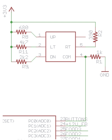
Here is a diagram of the rather simple switch circuit.
You should be able to test the Up, Down, Left, Right connectivity of the switch with a multimeter.
See the 6 holes for the switch in the middle of this image. The bottom right hole is circled white and is the common pin. The 4 orange circled holes are Up ( top left ), Left ( middle left ), Down ( bottom left ) and Right ( middle right, above white ). Measure between the common ( white ) pin and the 4 directional pins when you move the button in the corresponding direction.
The switch circuit is pretty simple, the 3.3v VCC is passed through 4 different value resistors to provide a different voltage on the L/R/U/D legs of the (normally open) switch. When you push the switch in one direction that pins voltage is passed to the ATMega, the ATMega knows which direction you pressed by what voltage is present. For instance, when you press UP the voltage that is on Pin1 should be on the Common (Output, pin 4) of the switch and the ATMega Pin23.
Here is a diagram of the rather simple switch circuit.
Thanks Steve_M and RalphTrimble! The provided information was very helpful in troubleshooting the switch issue. I was getting 0 voltage to the switch and traced the faulty connection back to the nearest capacitor. I swapped the capacitor and the switch is now working again properly.