Raspi 3A+ on a HM 4.0


Yes, that's a HM 4.0. I was trying to update my HM4.0 since it has the 4 line display and 4d printed case so I removed the original Pi and replaced it with a Raspi 3A+ but it's very unreliable and needs to be rebooted every couple days, then I might have to pull power and plug it back in several times.. I'm thinking maybe there is some noise either on the GPIO pins or in the power supply.

Thoughts on why the Pi3 would have issue where the original did not?
 
I would expect the pi3 to draw more power. The OKI 5V regulator should have no problem with that. Maybe check the 12V power supply you're using with it to ensure it's supplying enough juice.
 
Probably the only way you'll probably be able to diagnose this would be to hook a monitor and keyboard up to it and see what's going on. Just dropping off wifi every couple of days isn't normal, but there's not really any way to figure out what is going on if it just disappears and you have nothing to examine.

I really need to get another 3A+. The only one I have does a lot of duty outside with various ham and drone tasks and is fantastic. Taking it out of the case to hook it up to a HeaterMeter and let it sit for a while. I'll see if I can get to that this week to see if there's a systemic problem, but golly the 3A+ pulls such little power I can't imagine it would have a power issue.
 
Thanks all, FYI, the 3A+ worked just fine on the bench for a week or so. The issue began immediately upon plugging it into the HM. It took 3 or 4 connect/disconnect cycles before it booted. I'm assuming this as there was no green disk activity light.
 
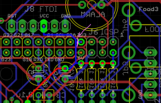
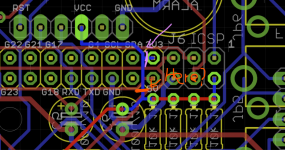
Something isn't right for sure, it should always boots up every time you plug power in. Do you have the 3.3V regulator installed on the HM4.0? If the regulator is installed maybe try cutting the trace on the bottom so the power isn't fed back into the Pi, which has its own 3.3V supply. This hasn't been connected since v4.1 to prevent them from fighting each other
1611768430891.png
 
No it is first pin. The image is a little confusing because there's the ICSP connector on the right which is its own thing, then the Pi header starts right after that with the 3V3 pin. I've just realized that because this is on the bottom and the Pi connector is there, it covers this trace so you won't be able to get to it. You can safely cut it where the blue trace goes up between the 5V pin though. It won't provide power to the FTDI connector any more, but I don't think that's really ever been needed. Make sure to leave the trace intact going to those 4x 10k resistors or else your probes will stop working.
 
Screenshot 2021-01-28 162312.png

Just making sure I understand. It's been quite a while since I built this, but I used to use 2 single row pin headers, If so, I might just be able to snip the end off and desolder just that one pin.
 
Yup that's where I was suggesting, sorry I didn't do a picture. You can just clip the 3V3 pin coming out of the Pi as well, they just need to not connect somehow.
 
Hooray! I hope that was it. I had originally connected the 3V3 to the HeaterMeter so that it could run off the Pi's power supply and save 40 cents on parts because I figured almost everyone would have a Pi connected. I later realized it was a lot easier to troubleshoot stuff if the HeaterMeter could be powered independently, but also found that they weren't the exact same voltage and thought it might mess something up. Seems like I might have been right.


Back
Top