RaspberryPi + LinkMeter blue sky discussion


Any possibility of dedicating an Arduino output for driving a damper solenoid for HM v4? I can see the possibilities with a 3d printed fan mount/automated damper.... - need 3 lines, grnd, fan and solenoid...

Or maybe a signal to control a servo? We could then have variable control for the damper . . .

So you don't think I say this in jest, I've found that for the best control of my smoker (UDS) I have to change my damper if I want to smoke at 200 vs 250 vs 300. I have it marked with a sharpie, but a servo would be even cooler
 
Last edited:
need 3 lines, grnd, fan and solenoid...
4 lines actually, because the fan runs high side so you can't use its gnd: 12V, FanGnd, Solenoid, Gnd. (Unless your solenoid can run on 12V in which case you can drive it high side too: 12V, FanGnd, SolenoidGnd).

I'd actually prefer if the whole system used stepper motors/servos to simply control the dampers but that would be a pretty radical departure from what we've got. I have to set my dampers depending on what my target temperature is too. The only pin we've got left on a HeaterMeterPi is Digital 7 (non-PWM) re-purposed from SOFTRESET and Digital 8 (non-PWM) re-purposed from LCD_DATA. I hate changing pin functions based on platform though. You should start a new thread to discuss it if you have some ideas though.
 
I've been lurking around this thread for a while, have a RPi and would like to start building my heatmeter ASAP.

Do you consider recommending the 4.0.3 Heatmeter PCB stable enough for end-users like me to build and use?
If so how would one obtain one?

I'm planning on dedicating my RPi to this project so removing the RCA video connector as mentioned in post 188 is not an issue.

I've also been considering potting as an alternative to a case and using a single, waterproof connector for *everything*...

I'm imagining both boards potted in a block of clear resin with embedded magnets for mounting...

Am I off my rocker?
 
I'm imagining both boards potted in a block of clear resin with embedded magnets for mounting...

I think that sounds like a great idea... do you plan to POT in the LCD entirely? Could be pretty sweet.

I'd make sure you have a way to remove/flash the SD Card though. I imagine if you hard wired in a USB card reader and had the USB pins output through the waterproof connector, you could leave the rpi plugged in and still be able to flash the card when the rpi is off. I may be wrong on that, but it seems viable.

Anyway, not a bad idea, I like it. I'll let bryan speak on the board, but I know it was good enough a while back if you don't mind a bit of hacking/fitment. Bryan also allowed for pin headers for fan outputs and such which is a really nice touch, so you don't need to get all the female connectors for grill probes, etc, you can use a pin header.

Also, I'm not sure if the wifi still freezes the boot, but that would be bad if it was potted in :p Hopefully if it is not fixed already it will be soon.
 
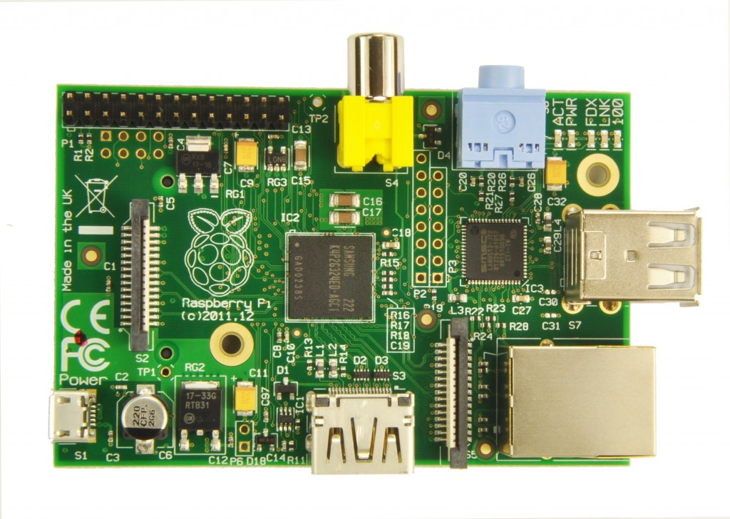
Oh, and if you swap the RCA over from the rPI, make sure you remember that you did that and don't hook the 12v fan output in through the RCA to your monitor. Oops :p. Luckily mine was in manual mode at 0% PWM. Not sure if the composite is 12v tolerant, but I'd guess not. The monitor flickered, but is fine. Maybe reusing the yellow RCA jack is not the best idea. Sharpie time :)

FYI,

I love the fan speed bar graph, but what is the yellow line that moves around? Moving average I guess?

Still strange functionality with the Image from the 30th with respect to wifi. Does not freeze on boot, but things are not happy. ifconfig essentially freezes, but the console is still responsive.

Web interface password stuff is working well now. Updating the firmware from the web page went off without a hitch. Hopefully going to test the new SRTP 1Hz update rate shortly.

I played with the 1Hz Update rate... working well, but I was thinking that setting the minimum fan speed on the web interface was actually the SRTP* start threshold... I see that they are not the same thing.. but I don't understand why they are really different settings. If I set the min fan speed at 40%, then I command 35% in manual mode, it just spins 40%, always on. If the SRTP started at the min fan speed, and chopped up the range of 0-MIN_FAN_SPEED into the nearest "on" time per 10 seconds, you would only have to set min fan speed, not srtp start percent. In this case, 4% would be on at MIN_FAN_SPEED for 1 second, off for 10, 8% on for 2 seconds, etc. I think that is how it will work when you set the SRTP value in the firmware, but I'm wondering if you ever need them to be different numbers (min fan speed and SRTP start percent). Am I just out of it tonight?

* SRTP = Split range time proportional, which is an easy way to say "when the fan goes on and off instead of variable speed control" (I hate when people use acronyms on forums and do not define them!)
 
Last edited:
The 4.0.4 PCB I'll have in github today and post CAM output for sending to Dorkbot. It just has a couple silk fixes and an nudge on one component over the 4.0.3s I have here.

The yellow pip on the fan bar graph is the 120 second exponential moving average of the fan speed.

You're right about the SRTP not working properly. There's a bug in the calculation that makes it run at [min speed] for almost all cases. Actually it is a bug in the original STRP code that just so happened to work properly at 10% min speed so I didn't look at it again when I changed the code to make it all variable. I'll have that fixed today too.

The Aug-30 build you pulled probably was from when I was re-shuffling the patches so it didn't have the network subsystem lock fix in it. Try the one from this morning. Actually, everything wifi related should work. In addition to not locking up you can also scan and join networks from the web interface. The scanning is just a temporary fix I threw in for testing though.
 
Schematics are now in github and CAM output (upload the zip to OSH Park / Dorkbot) is available at:
Schematics: http://capnbry.net/linkmeter/pcb/hm-4.0/
Parts List: https://github.com/CapnBry/HeaterMeter/wiki/HeaterMeter-4.0-Parts-List

I also have 2x v4.0.3 boards which have the labeling for CE0/CE1 swapped and no BBQ Boxy Robot printed on them. Electrically they are identical to the v4.0 boards. $13/ea shipped in a pretty white envelope.

I'll be finishing up the parts list and writing out some instructions this weekend.
 
Bryan -

Congratulations - I'll be looking forward to the instructions. I think I speak for a bunch of us when I say that your dedication to the project has really been outstanding. Thanks!
 
Hey nifty! Nice to see they're removing those fuses. I've got one of my boards with them jumpered and one standard with them attached and both work just as well in that I can't tell them apart functionally. The mounting holes are a nice addition though, and luckily I don't use the GPIO they moved to another place.

I wish they'd get to doing a version with wifi and no ethernet though! I bet one of the problems is clearing off enough board space to integrate the antennas with nothing obscuring them.
 
Hi Bryan! Looks like things are moving along nicely with the project. I am now in North Carolina. I was almost finished routing out my board when the motherboard on my laptop failed. I am going to have to wait until the movers come to get my desktop back so I can finish. The routing is super tough on my compact board. I had hit 90% complete with some pretty daunting routing challenges left. Most of the routing issues are related to the pin headers. I am not sure how I am going to make those connections. I might remove the pin headers that are not necessary (probes, blower). I do still want to maintain the ICSP and FTDI but I suppose I could do without the FTDI.
 
Hey Dave! I hope you enjoyed your cross-country trip with the family. Bad luck about the laptop though!

I'd say just junk all the connectors aside from the ICSP. With all your components being surface mount it would be really difficult to reprogram the chip with clip on leads. One thing I've seen is having the ICSP header on the edge of the board with 3 pads on the top and 3 on the bottom:
http://harizanov.com/2012/08/getting-funky/

Road trip was a blast!!!

I know you made a couple changes to the schematic since I started my design so I need to find that post and make those changes. I guess I can also reference the newest schematic. In any case I will probably harass you to look at my schematic.

I haven't seen that method of mounting pin headers....pretty cool. I was thinking I have enough room for a right angle pin header. Through holes are easier to route because you can access the component on both layers without vias.

I also want to make a custom case using Sketchup. I read the post about the custom linksys case and I just gotta learn how to do that! I bought a digital caliper now I need a micrometer.
 
I tried to make the commit messages in github for the schematic pretty explicit about what has changed, mostly so that I can remember what was different (click the commit, the messages are truncated in the list).

I just got an email as I typed this that my laser-cut parts are shipping today! I'm excited but I know I shouldn't be because I'm sure the'll be off by a tenth of an inch here or there. I also just bought a digital caliper after reading that instructable. That's all we need right?
Step 1) A digital caliper
Step 2) ???
Step 3) An awesome case that fits just right and looks professional

Did you see that the rPi 2.0 doesn't have that pinheader in the middle of the board populated? That should give you some more clearance in that area for taller components. What do you expect your final dimensions to be, roughly?
 
I just got an email as I typed this that my laser-cut parts are shipping today! I'm excited but I know I shouldn't be because I'm sure the'll be off by a tenth of an inch here or there. I also just bought a digital caliper after reading that instructable. That's all we need right?
Step 1) A digital caliper
Step 2) ???
Step 3) An awesome case that fits just right and looks professional

Arggggh....I am so far behind because of this move. I like to redesign your designs because I learn more. Maybe one day I will come up with something on my own.

I love love love my digital caliper. I have been using it since I started playing around with Sketchup. Step 2 would be a micrometer which is apparently helpful when the caliper is not. I have run into a couple situations where I could see it being helpful. Who doesn't need more tools!?!

Did you see that the rPi 2.0 doesn't have that pinheader in the middle of the board populated? That should give you some more clearance in that area for taller components. What do you expect your final dimensions to be, roughly?

Here it the v2:
sony-rasp-pi-1024x728.jpg


I did not see that until you said something. Any extra space would help. Mounting holes help. I am glad they are getting rid of those stupid polyfuses. I see they are also fixing some issues related to the USB hub...that one bit me. The non-ethernet model is suppose to be coming out soon and is $10 less. That will bring the price of the build down some more. More money for a custom case or to pay for the dongle?!

Looks like Sony is going to be manufacturing them from now on in a UK factory.

My intention is for the board to be roughly the size of the Raspberry Pi with some cut outs for components.
 
Last edited:
I have spent most of the day today playing with the board design. I did get it 100% routed. I still need to tweak some things and fix the silkscreen. I also need to figure out how I am going to support the board on the USB connector side of the Pi. I had originally planned to use the RCA jack but it was too tall so I replaced it with a low profile mono jack.

Here is the current draft Eagle brd:
HMPi_SMD.png


Now for the reason I am posting. I found a really cool script for Eagle called EagleUp (http://eagleup.wordpress.com/). It takes your board design and creates a 3-D version of your board in Sketchup. It works very well and will populate the components if it is available in their model library. Bryan, you might consider using this to reduce the amount of prototypes you have to make.

Here are the raw 3-D renders of the top and bottom of the board:

TOP
HMPi_SMD_Top.png


BOTTOM
HMPi_SMD_Btm.png
 
Last edited:
Bryan,

I got the newest 'official' image installed.

Two issues.. it seems it will not boot with wifi inserted still. I can't really get more info right now on error messages, etc, but I will as soon as I can.

Also, flashing the newest firmware for the HM via the web interface: Generic release/1/heatermeter.cpp.hex Fri Sep 09 2011 10:04:32 GMT-0500 (Central Daylight Time) d7f40fe5bb8a5a95a3d7d63e5b065c7e
causes a frozen screen on the LCD.

The older version: v3.2+ snapshots/trunk/heatermeter.cpp.hex Thu Aug 30 2012 08:14:07 GMT-0500 (Central Daylight Time) dcb78407076a823e965506bb789a9eb7
works well, but does not have the new fix for long PWM mode.

Keep up the good work. I'll try to put in some more time this week to get a better report of what is going on with wifi.
 
Last edited:
Also, flashing the newest firmware for the HM via the web interface: Generic release/1/heatermeter.cpp.hex Fri Sep 09 2011 10:04:32 GMT-0500 (Central Daylight Time) d7f40fe5bb8a5a95a3d7d63e5b065c7e
causes a frozen screen on the LCD.
That's because that's not the newest release, that's Sep 9, 2011 :)

I dunno what is up with the wifi, you'll have to give me some information about what's the last 20-30 lines of `dmesg`. Are you using the snapshot from
http://capnbry.net/linkmeter/snapshots/bcm2708/
 
I'll take these two boards. How can I send you funds (paypal, etc)...

I look forward to the parts list so I can get started.

-Jeff

Schematics are now in github and CAM output (upload the zip to OSH Park / Dorkbot) is available at:
Schematics: http://capnbry.net/linkmeter/pcb/hm-4.0/
Parts List: https://github.com/CapnBry/HeaterMeter/wiki/HeaterMeter-4.0-Parts-List

I also have 2x v4.0.3 boards which have the labeling for CE0/CE1 swapped and no BBQ Boxy Robot printed on them. Electrically they are identical to the v4.0 boards. $13/ea shipped in a pretty white envelope.

I'll be finishing up the parts list and writing out some instructions this weekend.


Back
Top