Hello I purchased my kit through the heaterMeter store and assembled it all on Sunday. Just got the opportunity today to load the software and power it up. I'm powering it through a USB cable attached to my computer, when powered up it has a red and yellow LED illuminated. The display first shows No pit probe then displays Pit: 19degF [100%]. When trying to register the device I get: No HeaterMeter found at your site. I have a Panda Ultra Wireless N USB Adapter, Model No. PAU03. I'm at a loss as what is my next step to try and get it functional.
You are using an out of date browser. It may not display this or other websites correctly.
You should upgrade or use an alternative browser.
You should upgrade or use an alternative browser.
New Heatmeter
- Thread starter TedK-MD
- Start date
Bryan Mayland
TVWBB Hall of Fame
Have you configured the wifi yet? If not then you need to plug in over ethernet to get it to show up for the first time. The 19F is typical because the Pit probe needs to be set to Thermocouple the first time you configure it as well.
As far as the button that could be an issue with it inserted backward maybe?
As far as the button that could be an issue with it inserted backward maybe?
Yea we have progress. I am now connected through Wi-Fi, I first connected a Ethernet cable to my router. Than it recognized it after that I proceeded through the Wi-Fi setup without any issues. Also changed Probe 0 to Thermocouple and now the display says No Pit Probe. I still have nothing happening when I try to use the 4-way button. I'm going to take it to work with me tomorrow and de-solder it, than reinstall it in the opposite orientation.
Last edited:
RalphTrimble
TVWBB Diamond Member
The center legs on the switch are offset just a bit to mark orientation, but not so much that it wont go in backwards if you force it... So maybe you've got the switch backwards?
The switch circuit itself is pretty simple, basically each direction you push the button has a different voltage on it (because it has a different value resistor to VCC), then the output connects to the ATMega. So a different voltage is sent to the ATMega depending on which direction you push the switch, pretty easy to troubleshoot if it comes to that.... but check the orientation first, if you look close you should be able to tell if you have it in right or have forced it in backward.
The switch circuit itself is pretty simple, basically each direction you push the button has a different voltage on it (because it has a different value resistor to VCC), then the output connects to the ATMega. So a different voltage is sent to the ATMega depending on which direction you push the switch, pretty easy to troubleshoot if it comes to that.... but check the orientation first, if you look close you should be able to tell if you have it in right or have forced it in backward.
RalphTrimble
TVWBB Diamond Member
click to the right until you see the setpoint field and then try to move the setpoint up and down... Does it work there?
RalphTrimble
TVWBB Diamond Member
The switch circuit is extremely simple, here is the schematic:
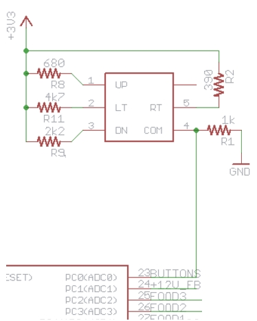
The leg on the bottom corner of the switch that is closest to the ATMega is the output (common) leg that connects to the ATMega, four other legs are attached to 3.3v through the various resistors. So you should be able to measure a different voltage on each of those four legs, and when you push the switch in each direction that voltage should appear on the output leg. You can also test continuity (with power off) of the switch by connecting one lead of your multimeter to the output leg and when you push the switch in each direction you should see a short to the associated leg of the switch.
The leg on the bottom corner of the switch that is closest to the ATMega is the output (common) leg that connects to the ATMega, four other legs are attached to 3.3v through the various resistors. So you should be able to measure a different voltage on each of those four legs, and when you push the switch in each direction that voltage should appear on the output leg. You can also test continuity (with power off) of the switch by connecting one lead of your multimeter to the output leg and when you push the switch in each direction you should see a short to the associated leg of the switch.
Last edited:
RalphTrimble
TVWBB Diamond Member
That's a bummer since the switch is discontinued and largely unavailable at this point. I think there was still one source left that had stock but I can't recall where, maybe somebody else will chime in on that?
EDIT: Bryan had the source linked on the HM Hardware page for the switch, they have over a thousand and only want a buck but the shipping may kill you...
http://www.onlinecomponents.com/alps-electric-skquaaa010.html?p=10114925&ref=amazonprodads
Ebay also has some listed for $3 including shipping (also with the option to "Make and offer")
Last edited:
Sorry for such a.long amount of time before an update. Got a replacement switch and installed it, great news now it works. Still need to do a test run on the Primo XL I built it for to see how it does. Next question when I hook everything up I can get the fan to come on but never see the servo move. Are there any settings that need to be changed to let it know you have a Servo? Should the servo be put in the fully closed or open position to start out? I am using the Tom Kole offset servo fan design. Thanks.
Definitely getting discouraged with this whole project. Don't know why no one answered my previous questions.
Decided to give it a try today to see how it would do, well after issues getting it to connect it finally did. But it basically makes my Internet useless. Doing a speed test it shows with the USB wireless adapter unhooked download of 91.12Mbps and upload of 92.39Mbps. After plugging in the adapter I get an download of 82.93Mbps and upload of 4.23Mbps. Tried to do the test with it plugged in two more times but it won't display any results basically locked it up.
I guess the only good thing is its been holding the temperature pretty steady for two hours so far on the grill. But the servo hasn't made any adjustments, even though the fan has ran at varying speeds. But I really built the heatermeter for the Wi-fi capability.
RalphTrimble
TVWBB Diamond Member
I guess Tom doesnt answer questions or offer support for his designs. Your valve could be binding, your servo SPD settings could be wrong, perhaps wrong enough to peg your servo and burn it out. Hard to tell, I don't think you have posted any info about your hm config?
Recently I made a post explaining how to calibrate the servo in the roto damper thread. You should give that a look see and try to get your servo calibrated. I haven't built up one of Toms dampers but the "offset rotary" damper is very similar in design to my roto damper, so the calibration should be pretty much the same.
As for your internet issues, and perhaps even your servo issues, sounds like you have some hardware problems and/or intermittent communication between your rPi and your HM. In this sort of instance I always suggest that you break things down, remove the rPi, remove the SDCard, remove the ATMega from its socket, then reflow solder on at least the main components at issue here... being the rPi header and the ATMega socket. Then reassemble and give it another try. Sometimes solder hasn't made its way to both sides of the board and you get flaky connections here and there that can make your rPi flake out. Or the rPi could not like your SD card, or your power could be flaky, could be an issue with your wifi router or the Edimax itself as well. Sorry I could be more specific and offer you a simple silver bullet to clear up your problems....
RalphTrimble
TVWBB Diamond Member
OK, with SPD numbers of 950-1750 your servo should be moving a good bit. The RD3 numbers usually run about 700-2100 and that is about 90% if the servos full range of motion. The SPD span for the RD3 is about 1400 and your setting is about 800, so I would guess your servo should be rotating roughly 90 degrees.
I would suggest you remove the servo from the damper to make sure the valve isn't making it stick, see if it rotates in free air. If it doesn't rotate in free air then you need to make sure your wiring is right for the servo. You can test continuity from the servo wires to the CAT5 jack on the HM board. Brown=gnd, red=5v, orange=servo. If you have continuity between the servo wires and those three pins on the HM CAT5 jack and the servo isnt moving then I am sorry to say you probably have a bad servo, or something wrong with your HM board.
With your settings the servo should move from your 950 position when the HM output is 0% to the 1750 position when the HM is 100%, its travel should mirror the HM output % linearly through that range. The only HM setting that would change that behavior is if you have selected the Open/Closed only option for the servo, in which case the servo would be in the 950 (closed) position when the HM output is 0%, then it would go wide open to the 1750 position while the HM was between 1-100% and not move again until the HM was back at 0%, at which time the servo should move back to the 950 (closed) position.
Hope this was helpful.
So I tried a different PS that was rated at 2A, things were looking good but within 5 minutes it locked my router for my internet back up. I took everything back apart, re-seated the memory card and the Raspberry-pi. Hooked everything back up with the same results, tried unhooking the Cat5 and then the pit temp probe with the same results. Pull the Wi-Fi adapter out and immediately the internet is good. Can a Cat5 cable be used in the empty female Cat5 socket to hook the Raspberry-Pi directly to my router to see if all works at that point, thus proving that the Wi-Fi adapter may be the issue? Also I still have no servo action, turned the temp up to turn the fan on, then turned the temp down to turn the fan off.