LCD Trouble


I originally built the HM 4.3 a couple of months ago and made a mistake with the screen (soldered in reverse). I removed it but damaged it a little so have been running without one. I've done 3 or 4 cooks from the web interface and everything else is working great.

I've just received a replacement screen, but it seems to display nothing with the contrast down, or a row of black squares (contrast up). Nothing in-between.

I've checked all the pins for continuity, gnd, cnt, d4, d5 etc. all seem to be ok.

I did manage to damage the gnd pad when removing the old screen, but its soldered on the reverse and continuity is good.
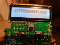
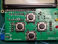
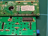
20210308_144612.jpg20210308_143954.jpg
20210308_143936.jpg
 
Last edited:
It might be worth mentioning both screens are
NHD-0216K1Z-FSW-FBW-L

but the old screen has a code;
500745HK-4518 and the new screen is 500733HK-4218
 
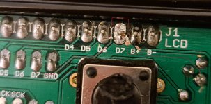
A couple of leads look bridged to me in the last photo to the right. Make sure those aren't bridged and try again if they are.
 
thanks for the suggestion. I think its just the flux that makes it look bridged (none are). I've cleaned up and re-flowed it anyway.

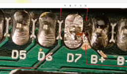
The D7 pin looked a little odd, so I've cleaned the solder off and it looks like it has a connection to drain 3 of the BS170 semiconductor as well as D7 on the shift register. is that correct?20210308_204006.jpg
 
Yeah D7 should only connect to D7. B+ is just 5V so if the bare trace is giving you a problem, you can just cut the trace further back and run a wire to bring 5V to B+.

If you're seeing that leg of the BS170 as connected to that pin, that's GND, so you've likely got some of the ground fill pour exposed and it is making contact with D7 and grounding it out. That will be tougher to fix considering how ground is everywhere around there. The D7 pin of the shift register might also be damaged in that case, because it is connected to ground and will over-current the pin (which can only drive like 50mA or something).
 
thanks Bryan.

I think this image shows the problem with D7 being grounded. It looks like the ground plane between D7 and B+ got bent and pushed into D7.
(I've removed the bridge now).
D7 only has continuity with D7 on the shift register.

It's still not working so I've ordered a new shift register as it my be damaged like you suggest.

Capture.PNG
 
You'd probably be able to tell if it was working with a multimeter. At least on mine, you can tell there's a signal going through once a second when it updates because the voltage jumps. You can test on both sides (the LCD side and the shift register side) to detect a break too.
 
Unfortunately I still haven't fixed this... I replaced the SN74HC595N.
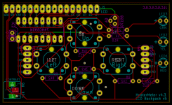
Using the schematic below, I probed all the pins with the shift register removed and then again when I installed the new one. Still does exactly the same :(

HeaterMeterLCD.Board.png
 
Ok, I'm an idiot. Installed the shift register on the woring side of the board. Luckily I bought a pack of 5.

All working now. Thanks for everyone's help :)
 
haha doh! That's awesome that you figured it out. You did it right the first time, I would have never considered that would have been a problem. I've definitely started doing that once myself 😳


Back
Top