HeaterMeter and not getting power to fan


RWeiche

New member
I just completed building my unit and it looks to be working as expected:
1. Can view through the internet
2. LCD works
3. My thermal couple works and is calling for 100% fan
I have verified that I have 12v at the initial connection and 12V near the LCD1 but don't see anything triggering the fan.
Let me know what I can check
I have some pic's but not sure how to include them.
Thanks for any info.
Randy
 
Last edited:
I just completed building my unit and it looks to be working as expected:
1. Can view through the internet
2. LCD works
3. My thermal couple works and is calling for 100% fan
I have verified that I have 12v at the initial connection and 12V near the LCD1 but don't see anything triggering the fan.
Let me know what I can check
I have some pic's but not sure how to include them.
Thanks for any info.
Randy
I did some more tracing and I have 12V to the 100uf/25v Electrolytic Cap on the + side but not seeing anything out of the - side?
Maybe a problem with the component?
 
Your post is confusing, perhaps that is why you have no replies.

You say your HM is working as expected, internet works, TC works, HM reads TC and turns the fan on 100% etc... so one has to read between the lines to see what your problem may be.

I assume you are saying the HM says 100% but the fan isn't actually moving? In that case the first thing you want to do is make sure you have connected the fan to the proper pins on your CAT5 jack. You need to use the BLOW and the GND pins. You should also check the fan settings in the HM config. For now set the blower to: PULSE Mode, on above 0, Min=0, Max=100, Startup Max=100. If the fan blows with this setting then change over to VOLTAGE Mode, if the fan stops blowing then you have a problem in your blower feedback circuit. If the fan doesn't blow in either mode then you have a problem with the fan driver circuit.

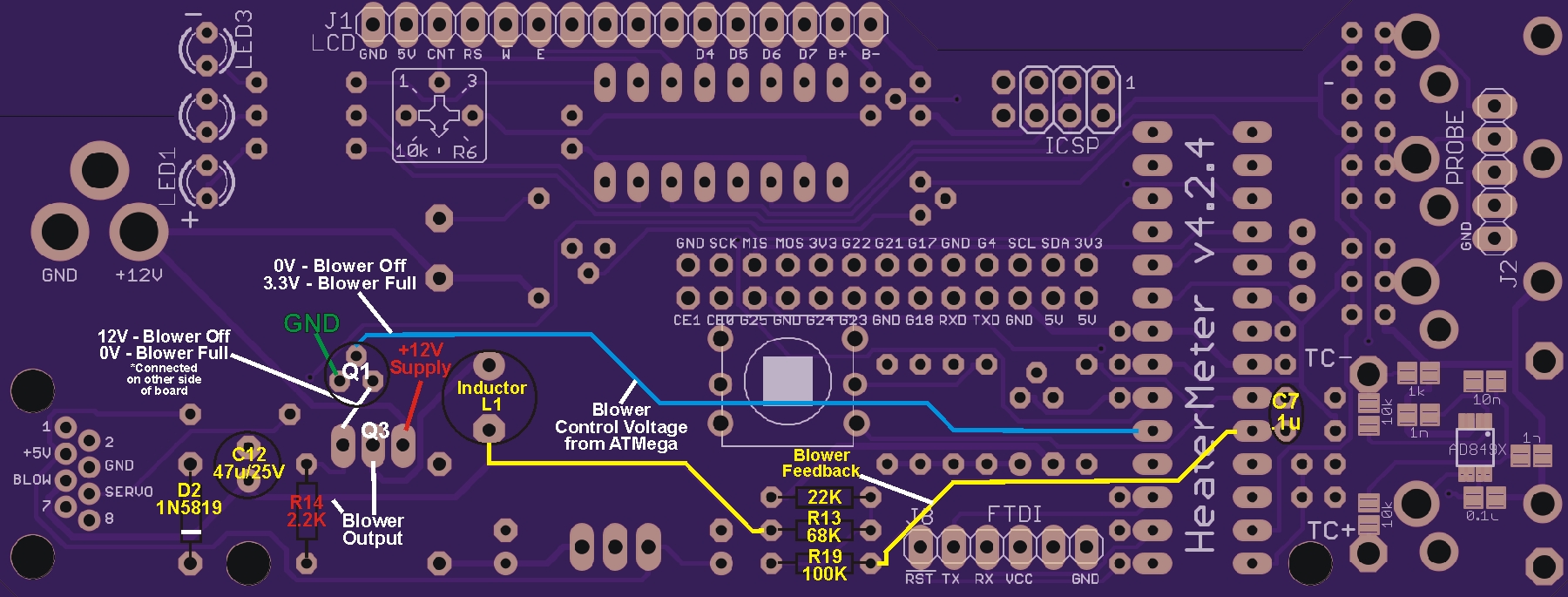
You didn't mention which version of the HM you built? Below is an image showing the HMv4.2.4 board with notes that identify the blower components, which part of the circuit they are in, and shows some voltages you would expect to see when the blower is at 0% and 100%. This should help you start with troubleshooting the circuit. I recommend troubleshooting with the blower set to Pulse mode because readings can be confusing in Voltage mode. If you have a HMv4.3 the blower circuit is exactly the same except the component(s) placement is different.

Post back a little more detail and somebody will try to help you get your HM up and running.

HM_Blower_Notes.jpg

Sorry for the lack of detail
I have the 4.3 version using pi 3b
When I start the unit it sees my thermal couple and says that it is requesting the fan at 100%
I have an internet cable plugged into the rj45 and checking the voltage on the blue/bluewhite wire pair I am see .2 to .3 volts which assume should be 12 volts.
I have checked the other pairs and have 4.5 volts so assume that is for the servo so not like all of the wires are dead.
Thanks for a start and will do some more checking.
Randy
 
You should first examine the board for solder bridges, bad solder joints, proper polarity on caps and diodes etc, posting high res pics as Steve suggested will allow others to help with that.

Next you should check the voltage on the center leg of Q1 ( after setting the HM config for the blower as I suggested). Even though the layout of the blower circuit is gonna be different on the HMv4.3 than the picture shown the center leg of Q1 should be easy to identify (the circuit is the same, just the layout is different). Read the DC volts to ground there when the HM is at 0% and 100%, compare to the notes on the troubleshooting diagram above. If your not getting the proper voltages there then check on Pin5 of the ATmega, this is where that voltage comes from. The next steps may vary depending on that result.

One thing you should do for sure is look at Q1 and make sure you have a BS170 there, they look exactly the same as other components such as the 3.3v regulator. You should see BS170 printed on the flat side.

Most of the time the problem will come out while checking the above, sometimes you've gotta go deeper... so go down the common path and post more info here if you are not able to resolve the problem.
 
Last edited:


Back
Top