REF Offset Repair


Dominick A

TVWBB Fan
My RDTC build was successful to the point that I got a solid reading on the TC and food probes while connected to my heatermeter. Along the way, I needed to remove the potentiometer, and in doing so ripped off the top right trace. After getting my TC readings squared away, I reinstalled the potentiometer and connected the broken trace over to the 1M resistor. I also removed the solder bridge I had placed in the top left traces labeled REFG.

After hooking things back up, the RDTC read no pit probe when no pit probe was plugged in. When I plugged it in, it read 38 degrees. I think I read this is the low point of the TC. This did not change when adjusting the potentiometer. Here is a pic of my board. Any ideas what's going on here or how I should troubleshoot?

https://drive.google.com/file/d/0BzSBmZGY0VqYcF9iRkJmZTRQS2M/view?usp=sharing
 
The REF offset control should allow you to raise the TC reading upward from room temp. When the control is completely counter clockwise the TC should register normal room temp, as you turn the control clockwise it should shoot up... So it sounds like you've got something wrong there in the REF circuit. It is fairly simple, check your work on the OP Amp IC on the other side of the board....
 
I'm looking for shorts and pins not lined up correctly, right?

I can't see any shorts and the pin alignment on the board looks ok. It doesn't seem possible to fit a probe on the inside pins to check for continuity. Is there anything else I should be looking for or able to test on the OP Amp IC? Does the OP AMP IC serve any other purpose other than for the REF Circuit? My TC was working fine before, I would rather not attempt to remove the TC jack to inspect that IC more closely.

Could the offset control be damaged? How would I test that?
 
Last edited:
the only purpose of the op amp is to provide a precision voltage reference which is applied to the REF pin of the TC amp chip. The circuit is extremely simple, there is just the op amp IC, the trim pot, the 1M resistor and a .1uf capacitor.

IF the REF Pin on the TC IC is connected to gnd the TC amp will output the voltage that corresponds to the actual temperature, if the REF Pin on the TC amp is fed a voltage instead the output voltage will be the voltage that corresponds to the actual temp PLUS the voltage applied to the REF pin. So you are looking at the REF Pin on the TC Amp IC to see if it is getting a voltage or ground or what...

That said, having helped you through a LOT of issues with this project my best advice to you is to just solder over that REFG jumper and use your RDTC without the REF offset circuit and call it a day...
 
I don't mean to leave you hanging here on this, but I have kinda exhausted my efforts here having helped you pretty much get all the way done with this project. At this point I think you have a working HM, working onboard TC, working RDTC board (minus the optional REF Offset) and working switch to choose the pit probe. I call that success over a whole bunch of major hurdles....

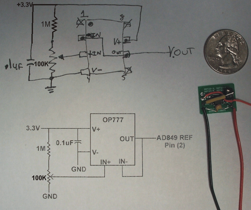
That said, here is a copy of the reference offset circuit I drew when I designed it. It shows the rather simple circuit on the bottom and the real world pinout in the hand drawn diagram above. You should be able to check the connections with continuity mode on your multi-meter (rdtc not being powered) and measure the voltages in the various spots (when powered) and perhaps find the problem.

As you can see the control input is a very simple voltage divider having about 1/10th of the voltage supply (3.3v) across the trim pot, so you should expect there to be 0VDC to about 0.33VDC on the wiper (single leg) of the potentiometer when swept from 0-100% respectively. There are a couple unused pins on the Op Amp IC so you can forget about those... The output is bridged across pins 2&6 and should sweep in a similar fashion with the input voltage when you rotate the trim pot.

TC_Ref_Driver_Final.jpg


Hopefully this info will help you figure out what is going on, but like I said earlier, the REF offset is totally optional and if I were you I might just solder back over the REFG jumper and call it a day...
 
Last edited:
Thanks Ralph - I was totally on board with your last assessment. I was out earlier when I read it and have since gotten home, bridged the REFG jumper and have everything put together!!!!

Now I'm trying to figure out some settings with the software as far as setting the fan to only go on after the damper is fully open, that sort of thing. I am calling this a major success so far and couldn't have done it without all of your help!
 
are you running the release version firmware or snapshot firmware?
Your HM config should have a setting for "On at Max Only" for the blower in the release version I think...
 
I flashed to Snapshot Version 20151026B. I see the on at Max only, but not the AC line filter that I read about earlier.
 
Yeah make sure you also install the latest snapshot linkmeter package (which contains the UI for the AC filter), then the snapshot AVR again (which contains fixes to the servo operation).


Back
Top