Version 2 of my homebrew controller


Hey guys, FYI, it's been a crazy week at work trying to wrap up before Thanksgiving. I'm off next week so I plan to spend a decent amount of time back on this project.

- John
 
Originally posted by john frank:
hmm... the only thing i see after completing this is the 3 files contained in "...\heatermeter\www\" no files from the parent directory are uploaded, also my mockup.html isn't converted to "". is this a concern? should i be disconnecting the the wishield before uploading the main sketch?
Yeah that's fine. It should upload the 3 files and then dump the header. The "mockup.html" I manually change to "" before replacing the flashfiles.h, but you only have to do that if you modify the web files. The think in quotes is the name of the file the webserver serves. Because you want mockup.html to be the default page, you change it to "". I keep it renamed mockup for testing because it is a lot easier to test it from a real web server than upload it every time you make a change.

I dunno what's up with all the LCD problems everyone is having. I've even built a second test circuit with an LCD with different components and have no issues with it :/
 
thanx bryan, that all makes sense!

i've been suspicious of this 2wire library for a while now... i have another project that has been plagued with elusive timing issues that no-one else seems to have trouble with. i just finished up a 3-wire shiftreg board and grabbed a 74ls164 from another manufacturer so we'll see in a sec or two!

thanks ed! this will be a big help!

i'll report back in a bit! cheers!
-sj
 
Sorry to be ignorant here but what is the issue with using a serial LCD module like the moderndevice one? I know the Arduino has only one UART but other than uploading code, what is it used for in this project? There are also projects that use a quad bilateral switch to toggle between multiple serial devices if really needed.

What am I missing?
 
Yes, many thanks to those who have contributed. I'm not going to list everyone because I'm sure that with 16 pages of thread I would leave someone out. Here are my thoughts (fwiw) on where we are now.

I like the idea of using a pre-built PIC based serial LCD controller because it is simple, supports all sorts of different display sizes without much Arduino code change, and has advanced features like big numbers, serial controlled contrast and brightness, graphics, etc.

After 1st building a prototype full size arduino, I went with the asynclabs yellowjacket mainly for cost but I also like the smaller size. The yellowjacket is the wame cost as the wishield2 but includes the arduino, all in an arduino nano sized package. I was happy with this until the Heatermeter code came out which used the flash in the WiShield2, unfortunately the yellowjacket does not have flash. The web interface on heatermeter is much better than the original but this got me thinking about what capabilities or limits there would be by having the Wishield present the interface to the user.

Then Ed had the great idea of using an old hacked Linksys to deliver the frontend and still have the arduino do the back end. Brilliant is all I can say, wish I would have thought of it. I was considering PCs and Atom boards but the OpenWRT route is definitely the way to go for many reasons.

Granted there are still a lot of things to work out like how the pieces will communicate and the Linux code. I do think the end result would be ideal, a small, reliable, inexpensive wireless temprature reader that can deliver pretty graphs of temps and control blowers and or electric elements.

So thanks again to all
 
rj, the main problem i see with the pic serial controller is when you forget to unplug it before uploading code to the arduino. its pretty easy to corrupt the firmware when dumping a new sketch to your board. (ask me how i know
icon_biggrin.gif
) reflashing the pic requires a pic programmer. the other obvious issue is price. otherwise, they are very easy to use and can save you a whole bunch of time!


i worked on mine a bit last night... 3 wire isn't working for reasons aside from HM code. one of the ribbon cables i bought had pins shorted so that might be part of it. Ed, your stripped down R36 has been running for hours now on another arduino with no apparent problems! i'll try to sort out that ribbon cable and convert my HM hardware to 2 wire. too many variables at the moment!

heres another shift register project that looks interesting. http://cjparish.blogspot.com/ (about 1/2 way down the page. 2 blogs.) he uses a 74hc595 instead of the ls164. i like the simplicity of his build, the fact that he uses all of the features of the LiquidCrystal library, and the transistor for backlight. i think the hc595 also uses less power which might be important for those of us who decide to run on batteries. just a thought... cheers!
-sj
 
thats great news ed! i've been a fan dd-wrt for many years. i have a original la fonera that should be up to the task.
-sj
 
Originally posted by john frank:
rj, the main problem i see with the pic serial controller is when you forget to unplug it before uploading code to the arduino. its pretty easy to corrupt the firmware when dumping a new sketch to your board. (ask me how i know
icon_biggrin.gif
) reflashing the pic requires a pic programmer. the other obvious issue is price. otherwise, they are very easy to use and can save you a whole bunch of time!
Good point on the serial, I'm now thinking of having the Linksys drive it with the second serial port. I'm putting some things together with a Java developer and should have some firm plans soon.
 
I've been following this thread for the last couple weeks when I stumbled onto it looking for a dual temp probe temp sensor that was wifi enabled. As I have a Traeger, I don't (currently) need temp control. However, I think I might be tweaking things to add a infra red or sonic range finder mounted to the pellet hopper lid to watch the pellet level instead of the motor control.

One other project that I'd like to play with once the basic setup is done, is a variation on this project from nerdkits.com
http://www.nerdkits.com/videos/meat_thermometer/
They use a little calculus to make a slow read meat thermometer considerably closer to an instant read type. I think this formula can be changed and since we know the final temp(what they are trying to solve for) but what we care about is time( when will the food be done) we could use the same idea to get an estimate of when the meat will reach its final temp.
Its a bit pointless as we have a bunch of ways to estimate cook times with experience, recipes, google, etc but how cool would that be to add to the LCD or web site.....

I'm holding off a bit to see if the 100% Arduino or the dd-wrt solution works out to be the best for me.

Keep up the good work guys.
 
Originally posted by Ed Pinnell:
<BLOCKQUOTE class="ip-ubbcode-quote"><div class="ip-ubbcode-quote-title">quote:</div><div class="ip-ubbcode-quote-content">Good point on the serial, I'm now thinking of having the Linksys drive it with the second serial port. I'm putting some things together with a Java developer and should have some firm plans soon.

I would be hesitant (at least during the development phase) to tie up both serial ports on the Linksys. tts/0 is used for the console and in my experimentation (with OpenWRT) I've had to use it to restore the router when something I changed made it impossible to talk to the router over TCP.

dd-WRT seems to be more user-friendly in that regard, and so far I haven't had to use tts/0, so I'm not sure that it is even available. By default, dd-WRT blocks telnet and ssh applications.

I do have a JTAG cable, just in case, but I haven't had to use it. Yet. That would be an option for you should you need to use both ports.

I am using v3 of the Linksys hardware (16MB RAM, 4MB flash memory). I've had an ongoing problem with my MMC/SDHC hack in that it wasn't always mounted properly during bootup. I think it has to do with the MMC card...I've tried three different cards, and some seem better than others, but none of them gave me the 100% reliability that I need. I have now done away with the card entirely by using Excel since I no longer need to serve web pages. </div></BLOCKQUOTE>

Thanks again for the valuable insight. I'd love to talk to you at some point about some of the issues you've run into. I would save us a lot of headaches a and wasting time on paths that don't pan out.

Thanks again.
 
i seem to have isolated a couple of my issues! the chip wasn't quite seated properly in the dip socket & a ribbon cable was improperly crimped by the manufacturer. 2-wire is working at the moment on my mock-up!

last night after lots of soldering and meter beeps, i finally decided it was time to look at things with the scope. hooked up the probes to pins and 8 & 4 and of course the LCD starts working!
icon_rolleyes.gif
must be a problem with either the pin or the trace on the shield... anywho, almost have all of the lcd bugs worked out on the mock-up. hopefully, i'll be moving on to wifi shortly after i sort out this trace!
-sj
 
One other project that I'd like to play with once the basic setup is done, is a variation on this project from nerdkits.com
http://www.nerdkits.com/videos/meat_thermometer/
They use a little calculus to make a slow read meat thermometer considerably closer to an instant read type. I think this formula can be changed and since we know the final temp(what they are trying to solve for) but what we care about is time( when will the food be done) we could use the same idea to get an estimate of when the meat will reach its final temp.
What's unusual about that link is they start talking exponential functions and calculus, but what all they end up doing is a simple amplified derivative. I've tried that and it doesn't produce very good results. Theirs looks great because they found the best constants to fit the data of the exact test. Mine looks something like this with a 20 minute time window and an "a" value of arrround 0.9
fit.png


Aside from that, BBQ doesn't behave like that. It follows an decaying exponential curve up to around 160F, where it sits for hours slowly climbing somewhat linearly until 180F and then starts increasing exponentially. Take my last Saturday as an example:
butt-20101120.png


What we can do with these numbers is look at the 9.2lb butt. At 5:58am it is 40F. What time will it hit 165F? If we consider that at one "time constant" we should have achieved 62% of temperature...
(165 - 40) * 0.62 = 77.5 + 40 = 117.5F
I reached 117.5F at 9:55am so our TC = 4 hours. Given an exponential decay reaches within 1.8% of its final value at 4 time constants, it should follow that I'd hit 162.75F at the 16 hour mark. However I hit it at 2:08pm, or at 8 hours 10 minutes. For some reason the math doesn't work out.
 
Originally posted by Bryan Mayland:

.... Theirs looks great because they found the best constants to fit the data of the exact test.

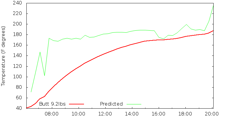
... Given an exponential decay reaches within 1.8% of its final value at 4 time constants, it should follow that I'd hit 162.75F at the 16 hour mark. However I hit it at 2:08pm, or at 8 hours 10 minutes. For some reason the math doesn't work out.

Sorry for the thread hyjack but I think we can wrap this up.

I've done a bit of research on this since my first post, the math doesn't work as well because we run into a "state change" of the fat and proteins in the meet. Just like it takes energy to go from 32 deg ice to 32 degree water, I think we start to get into some similar "state changes" in the meat as we start to render the fat, tendons and etc. This is what makes the meat do things like hold at 160 ish for a long time. That energy is not warming things up, its changing the state of the substance. I bet their predictions on nerdkits.com wouldn't work if the predicted temperature of the probe was on the other side of the melting point of the copper wire(for reasons besides the obvious failure of the apparatus).
 
I also find it remarkable that ambient temps in FL are in the 90s at 8:00p in November...here in SoCal, it's probably in the 50s or low 60s at that time. But I think you said your thermistor is inside the heatermeter enclosure, didn't you?
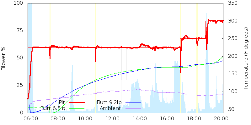
Yeah that's what it is. The thermistor is inside the case and actually about 1/4" from the MOSFET so it's not really a good indicator of anything besides showing it gets warm inside that project box. At the beginning you can see the 6.5lb butt probe (which isn't in meat for the first hour and a half) is at 56.7F while the Ambient reads 76.0F. Only one of those is accurate
icon_smile.gif


I needed to have the food ready around 8pm and normally I'd have no qualms about leaving HeaterMeter running overnight, but I was thinking I'd have to put the food on about 3-4am. I was expecting to be up all night the next night too, so I'd hate to fall asleep at my own party. I did also manage to find a bug in the manual lid mode that caused the temperature to ride too high when the automatic control returned.

David: I was hoping that I could model the cook as 3 separate phases.
Phase 1: Rise to plateau temp ~160F
Phase 2: Plateau time 160F-180F
Phase 3: Cook to doneness 180F-190/200F

What I was looking for was trying to fit the data to this curve for the phase 1:
160F = 40F + 120F(1 - e^(-t))
and solving for t would give me a constant that would scale directly with weight. Unfortunately though, the two butts in that graph don't fit the formula very well.
 
Ed's success in getting the Linksys embedded solution going has prompted me to order a new ASUS RT-N12. It uses 12V and has the onboard serial but is a couple inches smaller in one dimension than a WRT54L. It is $34 delivered vs $10 for a used Linksys, but still cheaper than the $62.50 shipped cost of the WiShield and I think it will work a lot better.
 
I probably won't get to it for a while though. I still have some work to do on the current HeaterMeter before I get into the router-based one.

I've done some DD-WRT development before, back when I was trying to get it to support the WNDR3300. And I've worked with the router serial ports before, back when I bricked a router in a somewhat unrelated piece of development.

4MB is a lot of space! I mean you don't need the big version of the firmware so I should have about 2MB free to play with right? I'm sitting here trying to squeeze alarms into HeaterMeter and they're triggering now but the LCD-based config is sucking down bytes left and right. Still only up to 29,282 without even disabling HTTP GET. Only 13,286 with no networking at all.

But I definitely won't have time to get to the router-based solution until after the New Year.
 
Hey guys, I'm back at it again! Last week I received the new LCD I ordered to replace my defective one. I also ordered some other parts to make my 2nd go at it a little cleaner.

During the process, I found a great source for cheap materials. I'm going to test out the $4.95 back-lit LCD they offer along with some other components that are much cheaper than Digikey and Sparkfun. If all works well I'll update my original BOM.

The source is: http://www.dipmicro.com
 
I've been following this thread for awhile now and finally decided to order the parts for this build. Looks like this is going to be a fun project.
 
Ed, might just be me but I don't see the pics? I do see the one in the post you made 2 days ago though.
 
Ed, you're amazing! Very well done!

In other news, last night I figured out how to control X10 modules using Arduino. Someone created an awesome library that made it a simple 15 min project.

I now have my hallway fans (used to circulate air from my fireplace) fully automatic to turn on and off depending on the ambient temperature in the room. Works flawlessly.

Fun stuff!


Back
Top