Version 2 of my homebrew controller


Looks pretty awesome Bryan.

I was wondering if it would be possible for you to post a parts list? I am kind of a newbie at this so I want to make sure I am reading the schematic correctly.
 
Absolutely. I've never done anything like this either. I'm a programmer, but have never tried to build any hardware so I would consider myself in the same boat you are. The first item in the list is the Digikey part number if I have it.

603-1117-ND: 12V DC Blower 60x25 6.7CFM
P22.0KCACT-ND: R1,R2,R10,R13 22kOhm 1/4W 1% resistors
: TR1 RadioShack 10kOhm thermistor
: R3,R4,R5 1kOhm 1/4W resistor
: R14 6.8Ohm 1/4W resistor (I used a 10Ohm)
: R6 10kOhm potentiometer
: R7 390Ohm 1/4W resistor
: R8 680Ohm 1/4W resistor
: R9 2.2kOhm 1/4W resistor
: R11 4.7kOhm 1/4W resistor
icon_biggrin.gif
1, D2 1N4001 50V 1A diode
:C1 22uF 25V electrolytic capacitor
IRF510PBF-ND:Q2 100V 5.6A power MOSFET
296-1647-5-ND: IC1 74LS164N 8 bit shift register IC

I got some parts from SparkFun as well
Arduino
16x2 5V Parallel LCD
Buttons

And of course the WiShield 2.0 WiFi

Regarding R6, you can just find the right resistance that makes the contrast on the LCD look right to you by trial and error. I have set mine and never adjusted it. The viewing angle is really good on the LCD.

Bonus! I was tuning my PID algorithm last night. The first section (before the first yellow bar) used just a PI control and I was getting a lot of overshoot while maintaining the temperature (230F). It would drop to 228/227 then the fan would kick up and the I term would keep the fan running even after it passed the setpoint so it would overshoot from 238-240. Even tuning it down I couldn't stop the overshoot.

The solution, which went in place in the flat area right before the yellow bar, was to use a 30 second moving average as the basis for the derivative component of the PID. Using just the "last input" that most PID controllers doesn't work because the difference between the current and previous value is never more than 1 degree and only exists for 1 tick. After I added the D component, I went to a 4 degree total swing, 229-233, but usually only 2 or 3 degrees per period. Interesting statistic: from low to low is almost always 5.5 minutes.

I'm thinking that now that I have the D component of my PID, the initial overshoot will also be much lower, as the PI-only algorithm will always overshoot in my configuration.
 
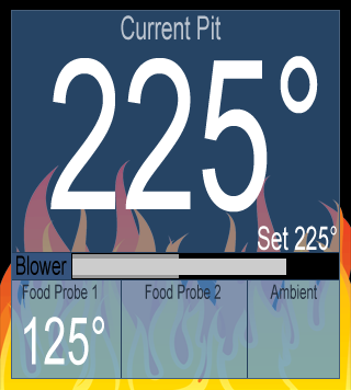
Annnd my web page with the temperatures updated via AJAX. Looks better (with transparency) in anything besides IE.

Something like this, for people who don't have another browser
mockup-v3.png
 
bryan, your project looks great! do you plan to publish your version of the code? im using very similar hardware and would like to see how you did the buttons and menu.

have you considered lowering the input voltage to fan? i think introducing less airflow over a longer period of time might cure your overshoot issue. lowering the fan voltage will slow the rotation but some 12v fans struggle starting up at lower voltages. somewhere between a 20? and 50? 2w resistor in series with the fan would be easy way to experiment with minimal hardware modification. just a thought!

cheers!
-sj
 
Thanks! Yeah I'm actually going to do a multipart post on my blog about how I did it and link all the code, schematics, and everything.

I've actually got a brisket on right now and it seems the overshoot issues are resolved with a 30 second moving average used as the basis for the derivative component. I think there is a bit of an issue with the accumulated error used for the I part not being able to decrease fast enough once the initial temperature is achieved though. It sort of rides on the high side the set temperature, passing the set point by +5 degrees or so then dropping down to +1 and slowly (5 minute period) bouncing back and forth between those as the I slowly degrades for about 30 minutes. I think Bob also had a similar issue based on some comments in his code. I think resetting the accumulated error the first time the temperature first reaches setpoint could be an easy work-around.

My system actually does a decent job of regulating fan speed. The fan will turn on at ~6% which if I remember correctly is around 6.5V and maxes out at 100% being 10.7V. I have a 1N4001 diode before the fan so it drops the voltage by 1.1V by itself. I'd like to experiment with shorting the diode and seeing what my voltage range ends up being. I'd like to keep the low end around the same place but raise the 100% to help reduce the startup time a bit. As it is running right now I'm seeing at most a 2 degree swing (225-227, 225 set) and the fan is mostly off, maxing at 10-12% every 5 minute cycle.

I'd also like to point out how **** cool it is to not have to check and adjust the grill every 30 minutes. You can see on the graphs how at some very spread out points the temperature in there drops by 5 degrees or so and the fan ramps up to compensate, I assume because the fire has stopped spreading in a direction because it reaches the edge of the pit. Eventually something else catches and everything goes back to normal for a couple hours. If I was actively manning the vents myself, I'm sure the temperature would have been all over the place as I overcompensate. As it is now, I only get 5 degrees off at the worst.
 
I'm so glad I found this forum, I built a version of Bob's as well but I used the yellowjacket 1.0 because it had everything I needed and was a lot smaller.
 
@James your site is definitely very cool. I considered doing something similar but it seems like a lot of work
icon_smile.gif
Do you have a service that polls the meters or is it uploaded after or what?

My status monitor page has taken hours to throw together; it has pretty much been my first foray into using CSS so there's been a lot of "why won't you go in the right place, little box!!" and unfortunately that fire PNG is like 12K so it takes 8-10 seconds or show to show up in Firefox. I've still got a lot of work to do, but what else are we supposed to do while we're not attending the grill, right?

I've had a little setback in that I was experimenting with the power on and fried something on my circuit board. I blew out two of the Arduino digital ports and for some reason now when my fan is in the "enough voltage to start spinning" transition period (5-6%) the LCD goes bonkers and fills with garbage. Good thing parts are cheap.
 
@bryan

I am a pretty seasoned web developer so the site wasn't too big a deal, I used CommunityEngine a free system that adds most of the social networking functionality.

Currently the website polls the controller every 60 seconds for data, all that is needed is a public ip address or url for your controller (and to conform to a json spec, that I'll be happy to publish).

the graphs are made using javascript, a jquery library named flot.

The site handles stoker data too, not that anyone in this thread cares
icon_wink.gif
 
Originally posted by Bryan Mayland:
Absolutely. I've never done anything like this either. I'm a programmer, but have never tried to build any hardware so I would consider myself in the same boat you are. The first item in the list is the Digikey part number if I have it.

Bryan,

Thanks so much for the detail you have posted (and thanks to Bob for the getting the project rolling).

I've had this project on my list for almost a year now based on Bob's original design. Last night I finally ordered the parts I need to build it (using many of the design changes that you incorporated).

Have you posted your source code anywhere for the Auduino and your web page?

I also plan to document the hardware and software build process from beginning to end. I may create a new "Instructable" detailing the process if someone else doesn't beat me to it (which by all means, please DO!). I will of course give credit where credit is due.

If anyone is interested, one of my past instructables on increasing the range of the Maverick ET-73 can be found HERE.
 
That looks great. Wish I knew about the yellow jacket. I would have tried it (even though size is not a concern for me)

Have you finished it yet?
 
Hardware is done, still working on software. Everything is the same as Bob's design except I switched to a serial LCD as it uses only 1, well maybe 2, pins. Would love to collaborate on software.
 
RJ, I'm definitely game for collaborating on the software even though our designs use slightly different hardware. I'm pretty familiar with the Arduino. I'll keep you posted on when I reach the point of writing the code.

John
 
Excellent, let me know if I can help in the process, I learned a few things getting to where I am now. I started work on an android app for my phone but its slow going, programming has changed a lot since my basic/pascal days.

FYI, great writeup on the maverick, I'll have to try it.
 
Originally posted by Bryan Mayland:
Annnd my web page with the temperatures updated via AJAX. Looks better (with transparency) in anything besides IE.

Something like this, for people who don't have another browser
mockup-v3.png

Bryan, I love what you've done with the interface. You have any experience on the Android platform? I am told its a lot like Java.
 
Thanks! I really wanted to do something different than just some edit boxes and the temperature in text next to the boxes. XmlHttpRequest and JSON are quite great for Arduino web stuff, because you serve a static page and then the job of filling in the data is handled by the web browser. A lot easier than trying to build the page manually on the Arduino. I am still working on the popups for being able to set probe names and temperatures but haven't had much time to work on it.

I'm working on using a buck converter to provide a linear 5v-11v power output instead of a PWM or a PWM with a capacitor on it. I've been having trouble with the component selection because for a 5v min and 180mA max with 4.5mA of ripple current, I calculated an inductor of like 7mH which is huge for such a small project. I bought an oscilloscope and it should be here Monday so I'm hoping that will provide me a much better idea of how the circuit is operating and I can get that done. After that, I'm going to hopefully design a PCB that snaps to the WiShield that will house the 5V regulator, AtMega chip, the buck converter and all the other circuitry for the probes, buttons, and LCD. Hopefully.

I do actually have some experience with Android programming. I love the platform and have a HTC Hero. It is Java programming and the design of the Android VM is pretty well done, making it pretty easy to pick up quickly. I considered an Android control app, but I decided a web-based client would be better because I could look at it on my laptop on the couch, or from the desktop in the office, or from a phone at the bar...

I haven't posted my code anywhere yet, sorry. I've been meaning to finish a series of articles about the construction and software for my blog but I get sidetracked by playing with all the cool Ardurino stuff. I'll pack up what I've got currently and post it tonight, with the caveat that it is still in flux and there's some things that don't work 100% (like editing the probe name using the buttons).

Something else for consideration, using a 22kOhm resistor for your probe voltage divider isn't probably the best choice. I made a nice graph that shows (based on my unchecked calculations) that at about 240F the probe only has a resolution of 0.8F. A smaller resistor value, such as 6.8k would give you a resolution of 0.3F.
Graph
 
Bryan, looks like you are making great progress. Take a look at the yellowjacket from asynclabs. Its a small substrate with the electronics of the wishield and an arduino. I then just made a shield for it with the 5v regulator, resistors for temp probes, and LCD IO.

I'd love to take a look at the code for your interface if/when you're ready to share. My code is pretty much the same as Bob's except the serial LCD.

At $55, the yellow jacket is a great deal.

Yellow Jacket 1.0


Back
Top