Originally posted by john frank:
Originally posted by S ROY:
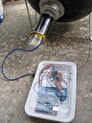
Hey John you care to share how you got the serial lcd working , Mine is in the mail and should be here in a few days along with a few other odds and ends.
haha, its kinda weird being asked for code when like 2 seconds ago i could have sworn i had no idea what's going on! lol!
keep in mind im no programmer, so some of this may be way wrong.... i installed the
SparkSoftLCD library to my Arduino Sketchbook Directory
/libraries/SparkSoftLCD/ and modified the lcd instances in bob's sketch to match those in the example sketch provided with the library. *note - i moved the LCD TX pin to pin 3 & the blower to pin 4.
<pre class="ip-ubbcode-code-pre">/****************************************************
BBQ Controller
For information see
http://hruska.us/tempmon
NOTES:
1) If USE_WISHIELD is defined, driver and server code is from:
http://asynclabs.com/wiki/inde...=WiShield_1.0_Driver
http://github.com/asynclabs/WiShield
Put all the files/directories under arduino/hardware/libraries/WiShield/ directory
in WiShield directory:
Edit apps-conf.h:
//Here we include the header file for the application(s) we use in our project.
//#define APP_WEBSERVER
//#define APP_WEBCLIENT
//#define APP_SOCKAPP
//#define APP_UDPAPP
#define APP_WISERVER
NOTE: The WiShield LED uses digital pin 9 to show that there is a
wifi connection. If an stardard 16x2 LCD is used, the only available pin for
blower PWM is pin 9. The LED jumper on the WiShield board should be
removed and the LED will not function.
If you are not using an LCD you can re-assign the blower PWM pin to 3, 5, or 6.
2) The WiShield by default uses INT0 (digital pin 2) for its interrupt. This code assumes that you
move the jumper on the WiShield from INT0 to D8 thus using D8 for the interrupt.
There is also a setup in the WiShield library file spi.h with the define:
//#define USE_DIG0_INTR // use digital pin 0
#define USE_DIG8_INTR // use digital pin 8
3) If USE_KEEPALIVE is defined, the IP address that you define in KEEPALIVE_ADDRESS will
be sent an http GET request every minute. If it returns data, all is well. If it
does not, the WiServer will be reset. Make sure the IP address you define here will
return valid data from an http GET request.
********** Edited for use with serial lcd sold by Sparkfun.com. ****************
Install the SparkSoftLCD library to the following directory: your arduino sketch folder /libraries/SparkSoftLCD/
The SparkSoftLCD library is available from:
http://openmoco.org/node/153
lcd = pin3
blower = pin4
*****************************************************/
#define USE_WISHIELD
// LCD transmit pin
#define LCD_TX 3
#define USE_KEEPALIVE
#define KEEPALIVE_ADDRESS 10, 1, 1, 50
#define BLOWER_PIN 4
#define DEFAULT_SETPOINT 225
//#include <avr/pgmspace.h>
#include <EEPROM.h>
#include "WiServer.h"
#include <SparkSoftLCD.h>
#define WIRELESS_MODE_INFRA 1
#define WIRELESS_MODE_ADHOC 2
//Wireless configuration parameters ----------------------------------------
unsigned char local_ip[] = { 10, 1, 2, 125 }; // IP address of WiShield
unsigned char gateway_ip[] = { 10, 1, 2, 1 }; // router or gateway IP address
unsigned char subnet_mask[] = { 255, 255, 255, 0 }; // subnet mask for the local network
unsigned char security_type = 1; // 0 - open; 1 - WEP; 2 - WPA; 3 - WPA2
// setup the wireless mode
// infrastructure - connect to AP
// adhoc - connect to another WiFi device
unsigned char wireless_mode = WIRELESS_MODE_INFRA;
unsigned char ssid_len;
unsigned char security_passphrase_len;
//NOTE: I have found that if I have an odd number of bytes of PROGMEM here then the board does not init
//at all. If you don't get a "Setup" message on the serial port, add a character to one of the
//PROGMEM fields and see if it helps......sigh
// WPA/WPA2 passphrase
const prog_char ssid[] PROGMEM = { "xxxx" }; // max 32 bytes
const prog_char security_passphrase[] PROGMEM = { "xxxxxxxxxxxxxxxxxxxx" }; // max 64 characters
// WEP 128-bit keys (modified to be 64 bit in library g2100.c func zg_write_wep_key()
prog_uchar wep_keys[] PROGMEM = { 0xDE, 0xAD, 0xBE, 0xEF, 0xFF, 0x00, 0x00,0x00, 0x00, 0x00, 0x00,0x00,0x00, // Key 0
0x00, 0x00, 0x00, 0x00, 0x00, 0x00, 0x00, 0x00, 0x00, 0x00,0x00,0x00,0x00, // Key 1
0x00, 0x00, 0x00, 0x00, 0x00, 0x00, 0x00, 0x00, 0x00, 0x00, 0x00,0x00,0x00, // Key 2
0x00, 0x00, 0x00, 0x00, 0x00, 0x00, 0x00, 0x00, 0x00, 0x00, 0x00, 0x00,0x00 }; // Key 3
prog_char html_open[] PROGMEM = "<html>";
prog_char html_close[] PROGMEM = "</html>";
prog_char html_form_close[] PROGMEM = "</form>";
prog_char html_settings_1[] PROGMEM =
"<form name=\"input\" action=\"setpoint\" method=\"get\">";
prog_char html_settings_2[] PROGMEM =
"Setpoint: <input type=\"text\" name=\"setpoint\" value=\"200\"><br>";
//prog_char html_settings_3[] PROGMEM = "P I D: <input type=\"text\" name=\"pid\"><br>";
prog_char html_settings_4[] PROGMEM = "<input type=\"Submit\">";
prog_char html_settings_5[] PROGMEM = "</form>";
//---------------------------------------------------------------------------
#ifdef LCD_TX 3
byte cur_bkl = 30;
boolean upd_disp = true;
SparkSoftLCD lcd = SparkSoftLCD(LCD_TX);
#endif // LCD_TX
#ifdef USE_KEEPALIVE && USE_WISHIELD
// IP address of a server you want to check connectivity to every minute
uint8 keepalive_ip[] = { KEEPALIVE_ADDRESS };
unsigned char keepalive_flag = 0;
GETrequest keepalive_get(keepalive_ip, 80, "keepalive-server", "/");
#endif //USE_KEEPALIVE
unsigned int current_millis_value = 0;
unsigned int previous_millis_value = 0;
unsigned int m = 0;
unsigned int minutes = 0;
unsigned int seconds = 0;
unsigned int hours = 0;
unsigned int food_temp = 0;
unsigned int pit_temp = 0;
unsigned int setpoint = DEFAULT_SETPOINT;
char wireless_stat='N';
int server_up = 0;
int server_resets = 0;
// Tuning constants for PID control.
// Set a constant to 0 to remove it's influence.
// So far, just using P=5 is looking good....
double PID_P = 5;
double PID_I = 0.02;
double PID_D = 0;
double PID_BIAS = 3;
// For integral, determine how often to update integral sum
// Integral is used to null out offset, so can be independent of offset size
int PID_I_FREQ = 6;
unsigned char fan_speed;
// EEPROM config data
typedef struct configData {
unsigned int configured;
unsigned int targetTemp;
};
configData config;
#ifdef USE_KEEPALIVE && USE_WISHIELD
// Function to handle data from the server
void processData(char* data, int len) {
static int state = 0;
char line[40];
char *ptr;
if (state == 0) {
// just grab first buffer, dump the rest
//sprintf(line, "Got %d bytes from processData\n", len);
//Serial.print(line);
//Serial.println(data);
state = 1;
// If we got anything valid, reset keepalive flag
if(len > 0) {
Serial.println("keepalive get received");
keepalive_flag = 0;
}
}
// When get is complete or fails, we get called with len=0. Reset state.
if (len == 0) {
state = 0;
}
}
#endif // USE_KEEPALIVE
void setup() {
Serial.begin(57600);
//Get stored setpoint from EEPROM. It is saved there whenver the web interface updates it
//If it has never been initialized, store the default setpoint into it and set it to
//initialized for next time.
readConfig();
if (config.configured != 0x1234) {
config.configured = 0x1234;
config.targetTemp = DEFAULT_SETPOINT;
writeConfig();
} else {
setpoint = config.targetTemp;
}
pinMode(BLOWER_PIN, OUTPUT);
#ifdef USE_KEEPALIVE && USE_WISHIELD
// Have the processData function called when data is returned by the server
keepalive_get.setReturnFunc(processData);
#endif //USE_KEEPALIVE
#ifdef LCD_TX
pinMode(LCD_TX, OUTPUT);
lcd.begin(9600);
lcd.clear();
// hidden cursor
lcd.cursor(0);
#endif //LCD_TX
}
void loop() {
// Update clock time, run any pending timer routines,
// and do web server processing
update_time();
#ifdef USE_WISHIELD
if(!server_up) {
server_up = WiServer.async_init(sendMyPage, 0);
//WiServer.enableVerboseMode(true);
} else {
//WiServer.enableVerboseMode(true);
WiServer.server_task();
}
#endif // USE_WISHIELD
}
void readConfig() {
int i = sizeof(configData) - 1;
unsigned char * p = i + (unsigned char *)&config;
while (i >=0) {
*(p--) = EEPROM.read(i--);
}
}
void writeConfig() {
int i = sizeof(configData) - 1;
unsigned char * p = i + (unsigned char *)&config;
while (i >=0) {
EEPROM.write(i--, *(p--));
}
}
#ifdef USE_WISHIELD
void web_print_stats() {
char line[80];
double fan_pctg;
fan_pctg = (double) fan_speed / (double) 255;
sprintf(line, "<h2>Setpoint: %d</h2>", setpoint);
WiServer.print(line);
sprintf(line, "<h2>Pit temp : %d</h2>", pit_temp);
WiServer.print(line);
sprintf(line, "<h2>Fan speed: %d%%</h2>", (int) (100 * ((double) fan_speed
/ (double) 255)));
WiServer.print(line);
sprintf(line, "<h2>Server restarts: %d</h2>", server_resets);
WiServer.print(line);
sprintf(line, "<h2>Elapsed time: %2.2d:%2.2d:%2.2d</h2>", hours, minutes,
seconds);
WiServer.print(line);
}
// This is our page serving function that generates web pages
boolean sendMyPage(char* URL) {
char line[80];
// Check if the requested URL matches "/" and if so give generic info page
if (strcmp(URL, "/") == 0) {
WiServer.print_P(html_open);
web_print_stats();
WiServer.print_P(html_close);
return true;
}
// If URL is "/data" then output one line compact data string for logging
if (strcmp(URL, "/data") == 0) {
WiServer.print_P(html_open);
sprintf(line, ",%d,%d,%d,%d,%2.2d:%2.2d:%2.2d,\n", pit_temp, food_temp,
setpoint, fan_speed * 100 / 255, hours, minutes, seconds);
WiServer.print(line);
WiServer.print_P(html_close);
return true;
}
// If URL is "/reset" then reset web server
if (strcmp(URL, "/reset") == 0) {
WiServer.init(sendMyPage);
return true;
}
// Present a form for setting variables via web page....should have a password....
if (strcmp(URL, "/setup") == 0) {
WiServer.print_P(html_open);
WiServer.print_P(html_settings_1);
WiServer.print_P(html_settings_2);
// WiServer.print_P(html_settings_3);
WiServer.print_P(html_settings_4);
WiServer.print_P(html_settings_5);
WiServer.print_P(html_close);
return true;
}
// This is the URL that is returned from the "/setup" form. Set the variables.
if (strncmp(URL, "/setpoint", 8) == 0) {
sscanf(URL, "/setpoint?setpoint=%d", &setpoint);
config.targetTemp = setpoint;
writeConfig();
WiServer.print_P(html_open);
web_print_stats();
WiServer.print_P(html_close);
return true;
}
// URL not found
WiServer.print_P(html_open);
WiServer.print("ERROR: Improperly formatted URL<p>");
WiServer.print(URL);
WiServer.print_P(html_close);
return true;
}
#endif // USE_WISHIELD
void hours_tick() {
}
void minutes_tick() {
static unsigned char counter = 0;
#ifdef USE_WISHIELD
if (WiServer.connection_up()) {
wireless_stat = 'W';
} else {
// It's down...try to restart it //
wireless_stat = 'N';
server_up = WiServer.async_init(sendMyPage, 1);
server_resets++;
//WiServer.enableVerboseMode(true);
}
#ifdef USE_KEEPALIVE && USER_WISHIELD
if(keepalive_flag) {
// It has been one minute and no response - reset WiServer
Serial.println("No response - resetting WiServer");
server_up = WiServer.async_init(sendMyPage, 1);
keepalive_flag = 0;
server_resets++;
} else {
// Send request to the keepalive ip and make sure we can still talk
Serial.println("Sending keepalive GET");
keepalive_flag = 1;
keepalive_get.submit();
}
#endif // USE_KEEPALIVE
#endif // USE_WISHIELD
if (counter++ == 5) {
// 5 minute sanity check
counter = 0;
#ifdef USE_WISHIELD
if (WiServer.connection_up()) {
wireless_stat = 'W';
} else {
// It's down...try to restart it //
wireless_stat = 'N';
server_up = WiServer.async_init(sendMyPage, 1);
server_resets++;
//WiServer.enableVerboseMode(true);
}
#endif // USE_WISHIELD
//sanity_check = 1;
}
Serial.println("Minutes tick");
}
// Run this every second. Inside it could also have static counters to run things on
// other multiples of seconds.
void seconds_tick() {
char line[60];
#ifdef USE_WISHIELD
if (WiServer.connection_up()) {
wireless_stat = 'W';
} else {
wireless_stat = 'N';
}
#endif // USE_WISHIELD
pit_temp = thermister_temp(analogRead(5));
food_temp = thermister_temp(analogRead(4));
fan_speed = DoControlAlgorithm(setpoint, pit_temp);
analogWrite(BLOWER_PIN, fan_speed);
sprintf(line, "%2.2d:%2.2d:%2.2d Pit=%3d Food=%3d Setpoint=%d Blower=%d %c ", hours, minutes, seconds, pit_temp, food_temp, setpoint, fan_speed*100/255, wireless_stat);
Serial.println(line);
#ifdef LCD_TX
lcd.clear();
lcd.cursor(0);
sprintf(line, "%2.2d:%2.2d %3d%c/%3d%c", hours, minutes, pit_temp, 0xDF,
setpoint, 0xDF);
lcd.print(line);
lcd.cursorTo(2,1);
sprintf(line, "M=%3d%c B=%2.2d%% %c", food_temp, 0xDF, fan_speed * 100 / 255, wireless_stat);
lcd.print(line);
#endif // LCD_TX
}
void update_time() {
static unsigned char last_seconds = 0;
static unsigned char last_minutes = 0;
static unsigned char last_hours = 0;
current_millis_value = millis();
m += current_millis_value - previous_millis_value;
seconds += m / 1000;
minutes += seconds / 60;
hours += minutes / 60;
if (seconds > last_seconds) {
last_seconds = seconds % 60;
seconds_tick();
}
if (minutes > last_minutes) {
last_minutes = minutes % 60;
minutes_tick();
}
if (hours > last_hours) {
last_hours = hours % 24;
hours_tick();
}
m = m % 1000;
seconds = seconds % 60;
minutes = minutes % 60;
hours = hours % 24;
previous_millis_value = current_millis_value;
}
unsigned char DoControlAlgorithm(int setPoint, int currentTemp) {
unsigned char fanSpeed = 0;
// state we need to save
static float integralSum = 0, prevError = 0;
static unsigned char integralCount = 0;
float error, proportional, integral = 0;
float derivative, control, prelimitcontrol;
// calculate the current error
error = setPoint - currentTemp;
// proportional term
proportional = PID_P * error;
// derivative
derivative = error - prevError;
derivative = derivative * PID_D;
prevError = error;
// control value is % (0 - 100)
control = PID_BIAS + proportional + derivative;
prelimitcontrol = control;
// integral term. see if it's time to do an integral update (and
// that integral term isn't 0)
if (++integralCount >= PID_I_FREQ) {
integralCount = 0;
// integral accumulation - include "anti windup" test.
// Don't change the integral being accumulated if the control value is
// already at 100% and the integral error is positive (which would increase
// the control value even more), and don't change the integral sum if
// the control value is already at 0% and the integral error is negative
// (which would decrease the control value even more)
// Since we've already added it in, remove it here if necessary
if (error >= 0) {
integral = PID_I * error;
if (control + integralSum < 100) {
// experiment
integralSum += integral;
}
} else {
// A possibility to try here....if error is negative, increase the rate
// that we slow the fan down by multiplying PID_I
// i.e. integral = PID_I*2 * error;
integral = PID_I * error;
if (control + integralSum > 0) {
integralSum += integral;
}
}
}
control += integralSum;
// limit control
if (control > 100)
control = 100;
else if (control < 0)
control = 0;
// convert to PWM setting ( 0 - 255), (50 is to round instead of truncate)
fanSpeed = ((control * 255) + 50) / 100;
return fanSpeed;
}
int thermister_temp(int aval) {
double R, T;
// These were calculated from the thermister data sheet
// A = 2.3067434E-4;
// B = 2.3696596E-4;
// C = 1.2636414E-7;
//
// This is the value of the other half of the voltage divider
// Rknown = 22200;
// Do the log once so as not to do it 4 times in the equation
// R = log(((1024/(double)aval)-1)*(double)22200);
R = log((1 / ((1024 / (double) aval) - 1)) * (double) 22200);
//lcd.print("A="); lcd.print(aval); lcd.print(" R="); lcd.print(R);
// Compute degrees C
T = (1 / ((2.3067434E-4) + (2.3696596E-4) * R + (1.2636414E-7) * R * R * R)) - 273.25;
// return degrees F
return ((int) ((T * 9.0) / 5.0 + 32.0));
}
void CelsiusToFarenheit(float const tCel, float &tFar) {
tFar = tCel * 1.8 + 32;
}
</pre>