New build - LCD question


I might be ready to throw in the towel on this thing. At least the LCD. I tried to remove the LCD for about 3 hours tonight and didn't really get anywhere.

I've spent so many hours on this thing. It feels like I haven't seen my family in weeks. Lol

The voltages are still off on the probe pins. If I can get one food probe working right for this weekend, I'll be happy.

I also have to figure out how to put together the RD3 and hopefully get that working.
 
I'm sorry you are frustrated, but understand.
Pin by pin is probably the best way to attack the display header. Heat the solder joint on a pin, push pin through the board while solder is molten with some pick like element and pull with pliers when you can get ahold of it. Then do cleanup after you've got all the pins out. Not a fun job really so... Displays, over rated, right? LOL Just kidding... but you can use the HM without the display IF it is really working.
Did you do the SMD soldering yourself on the TC pit probe? Have you connected a blower to test?
 
Update:

I bought a new HM kit and started over. I'll probably go back and work on the old one later. I did figure out that the capacitors all in backwards, so I need to fix that, too.

I put the new kit together and... still no text on the LCD screen.

It doesn't appear that the ATMega is flashing - I don't have the post-flash bouncing voltages.

I followed the software load instructions, but the message doesn't seem to be getting to the ATMega.
 
Man, IDK how I missed the caps being backward, I appalogize for not catching that. That is an easy fix, the larger caps are among the easiest items on the board to remove and reverse position. The diodes both need to have their bars facing down toward the edge of the board.
 
So, on the NEW build...

First of all, what rPi are you using?

What SD Card are you using?

Assuming the software load instructions you followed say roughly "connect SD Card to PC card reader, run Win32DiskImager, load HM .img file, WRITE to SD. (Make sure write protect is OFF on the SD Card).

I just want to make sure we are starting off with good communication on what is happening here....

That SHOULD put the software on the SD card for you....

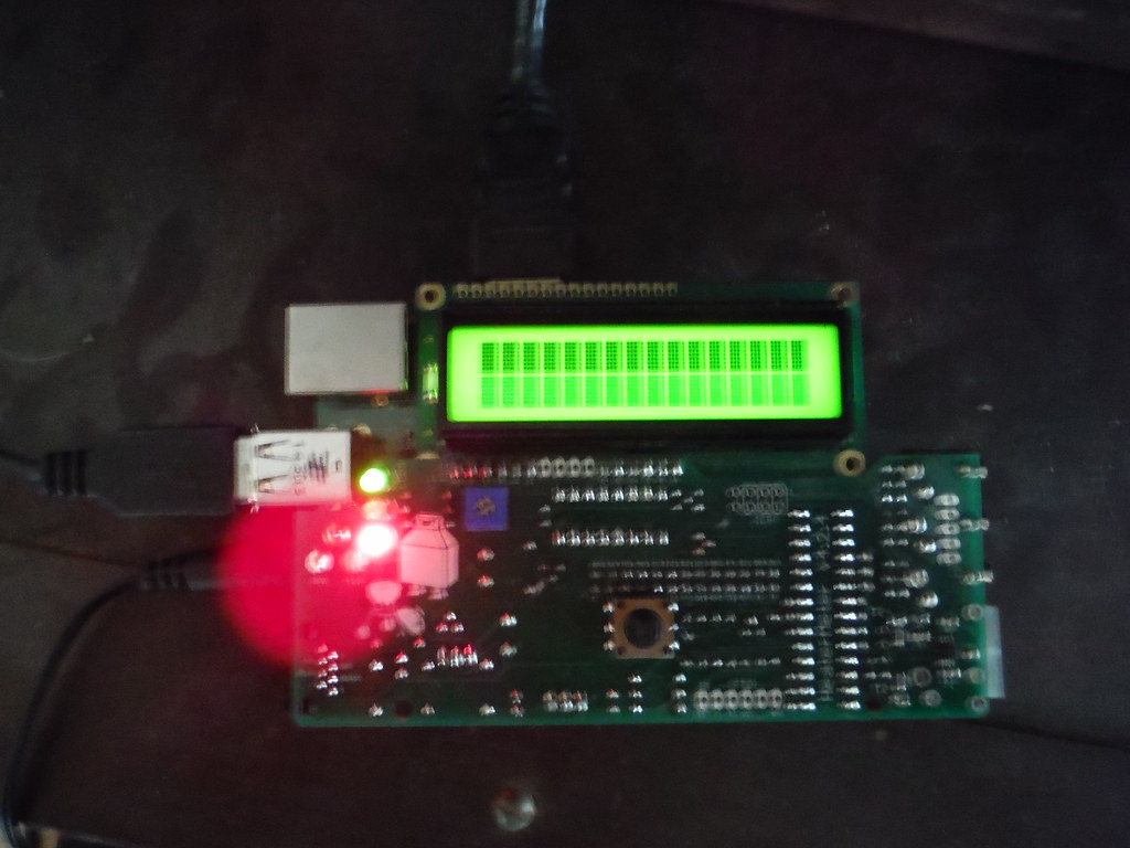
Now assuming the HM board is built properly, and the rPi is connected to it properly, it SHOULD flash the ATMega at first boot, then reboot and the HM board should come to life.... Apparently it didn't....

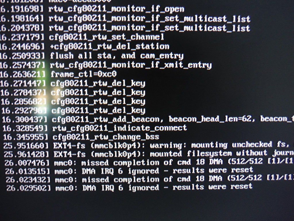
It's probably a good idea to take a look at what is going on in the rPi. Do you have a screen with HDMI input and an HDMI cable you can use to connect the rPi to it? If so, connect the rPi to the screen and boot and see what you have on the screen. Post a pic perhaps.

If you have a USB keyboard you can connect that to the rPi as well and then you can manually run the command to force the flashing of the ATMega... Something you shouldn't have to do (with recent software releases) but it's worth a try even if just to see the result.

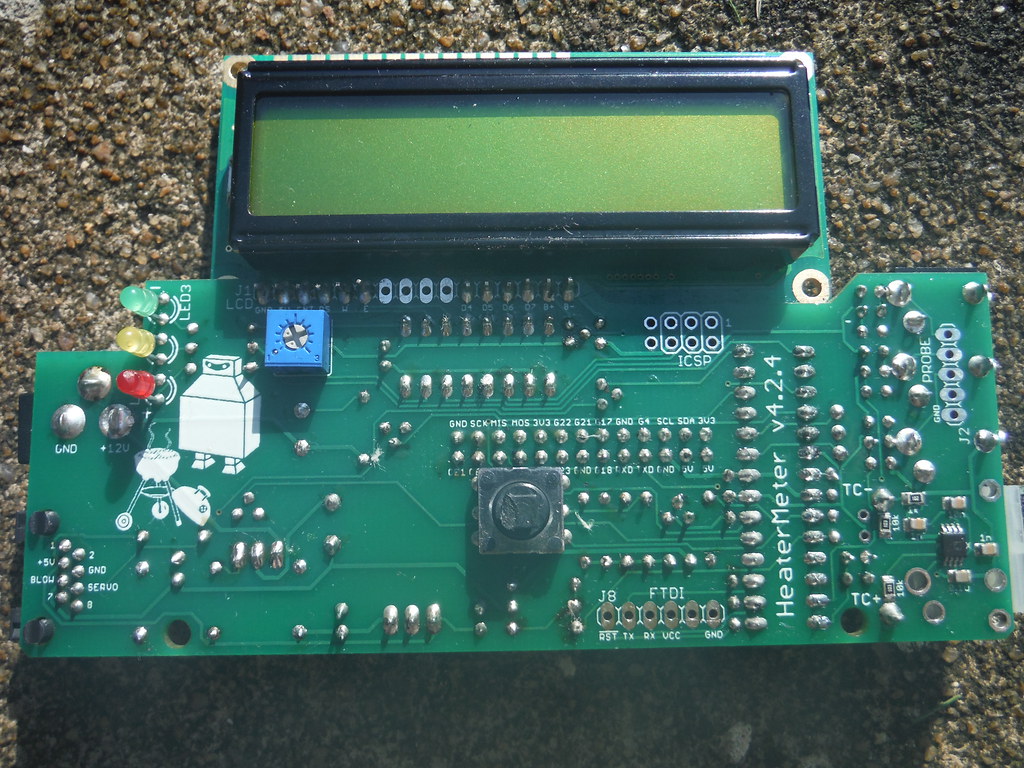
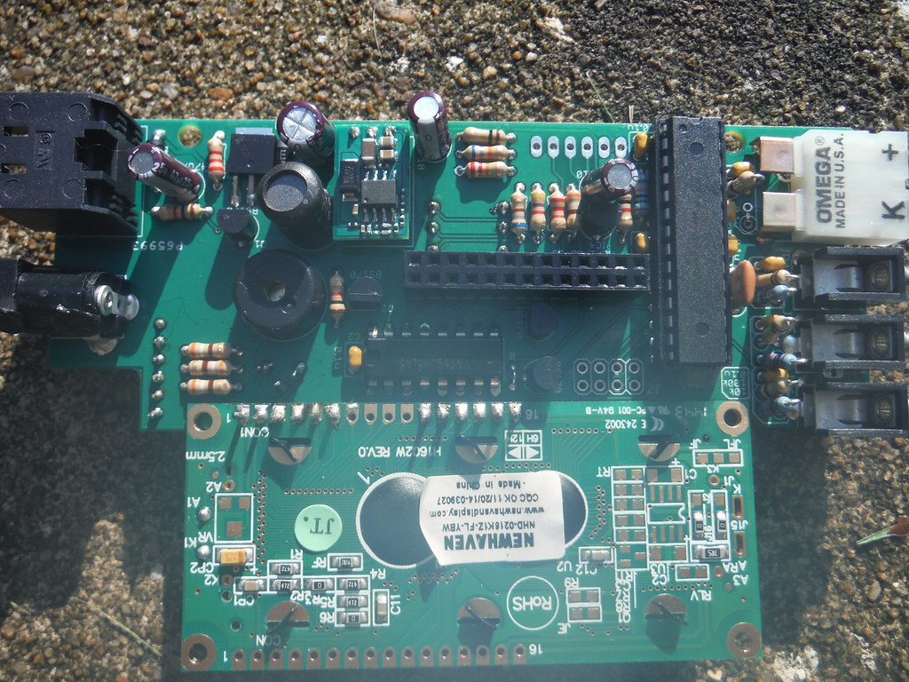
And of coarse some pics of the new build would be helpful as well.

I've been waiting for you to report back here, was going to make a one time offer, if you can't get your HM rolling send it to me and pay postage both ways and pay for any parts I need to fix it and I will do my level best to fix it for you... for free... I hate to see someone struggle like this for so long, but troubleshooting from afar isn't easy sometimes...
 
Post close up pictures of your board. We would have seen backwards caps on the first board if we had some pictures. It really helps with troubleshooting

Front and Back as close as you can with good lighting and in focus
 
I've tried both a Sandisk and a Sony 8GB card. Tried 2 different computers to load them, too - only because my work laptop crashed last week. :S

The stuff definitely gets loaded onto the SD card following the Win32DiskImager process.

Here are some images

DSCF2291 by cschaaf33, on Flickr
rPi bootup - I let this go for a few minutes and this is where it seemed to stop adding new lines.

DSCF2292 by cschaaf33, on Flickr
Top of the board

DSCF2295 by cschaaf33, on Flickr
Bottom of the board
 
Last edited by a moderator:
OK, looks like linkmeter is loading on the rPi, mine stops after the "mounted filesystem without journal" line, but if boot with a USB keyboard attached I get the extra couple lines about DMA IRQ 6 too...

Assuming you have a USB keyboard plugged in too, if not get one connected. If you hit the ENTER key you should get a command prompt. At the command prompt type:

avrupdate /lib/firmware/hm.hex

This command will tell the HM to flash the AVR (ATMega), it should erase and then write. Give it a try and lets see what it reports back.

My very first HM build went kinda rocky, very similar to what you are experiencing. I wrote a post about what I learned and how I got it going, you might get some info from reading it.

http://tvwbb.com/showthread.php?409...ntual-SUCCESS!&highlight=initial+boot+success

Although I believe Bryan has since changed something with the Linkmeter software that should make it be more aggressive about programming the ATMega, so it should be less likely you would need to force flash it... but it's worth a try if not just to see what linkmeter reports back.
 
Last edited:
Something happened, just not enough. ;)

I connected a keyboard and entered the command. The HM 'blinked' twice and the load said it was successful.

Still no text displayed on the LCD, just the blocks. And the voltages aren't bouncing.

DSCF2300 by cschaaf33, on Flickr
 
Last edited by a moderator:
This is a new ATMega chip and LCD, not the same ones from the previous build? It seems as though the rPi is able to flash it...

What model rPi are you using?

This is a KIT you have right? No parts substitutions?

It would seem the thing should be working, can you connect with the wired LAN, if so, does it save settings, register temps etc properly?
 
Last edited:
Here is the rPi I bought

The HM is a all new kit, I didn't use any of the old parts, nor are there any substitutions. The only 'old' piece is the rPi.

I'll try to connect to a network tonight or some time this week

Thanks
 
OK, I'll try to stay tuned for your response, best if we do some rapid fire testing and reply to try and nail this down rather than having such delay between posting. I am kinda shocked that you have built two kits that have the exact identical failure, kinda blows my mind and makes me wonder what the hell we are missing?
 
He's posted pics attached to linked text, harder to spot... I didn't spot anything out of place. Can't really tell if the diode closest to the CAT5 jack has the bar facing down in the pic for sure but I assume it is, like the other diode near there.
 
Last edited:
Please post some pictures if you want help, they will help immensely

Hey John

I posted links to my pictures on my Flickr account in this post: http://tvwbb.com/showthread.php?61130-New-build-LCD-question&p=681439&viewfull=1#post681439. Sorry, I tred posting pictures directly, but couldn't get them to show up.

Ralph

I was able to log into the HM, configure my probes, and set up WiFi. Everything stayed after a power cycle.

The probes act pretty much exactly like my first build attempt. Temperature goes up when I grab one, and down when I let go. Probe 1 runs a bit hot - it shows 101 degrees when I am holding it. Probe 2 looks dead on. It shows 95 when I hold it, same reading I get with my Thermapen.
 
So the HM is working and twice you have a bad LCD? I just dont get it!

I know we've gone over things, check contrast pot etc. If the probes read room temp and go up when you hold them then the HM is WORKING...

Here is the section of the schematic that shows the LCD connections. It flows from the ATMega to the Shift Register IC to the LCD. I have traced out the connections you should look at, in addition to the voltage supplies and gnd etc on the LCD header.

LCD.jpg
 
Last edited:
He's posted pics attached to linked text, harder to spot...
I've embedded these images so they are now visible in the thread.

CSchaaf, in Flickr, click the Share icon on your photo (a curved arrow on the bottom right). Select BBCode and use the dropdown to select "Large - 1024 x 768". Ctrl-C to copy the code and Ctrl-V to paste it into your post. This will embedded your photo in the post.

Good luck with your project.
 
I've embedded these images so they are now visible in the thread.

CSchaaf, click the Share icon in Flickr on your photo (a curved arrow on the bottom right). Select BBCode and use the dropdown to select "Large - 1024 x 768". Ctrl-C to copy the code and Ctrl-V to paste it into your post. This will embedded your photo in the post.

Good luck with your project.
Thanks


I saw the pictures, other then, what I believe looks like paper towel or something from cleaning, I also don't see anything except maybe one spot on your LCD E connection on the LCD side of the HM. Your best bet is to look at the Schematic and use a multimeter to check continuity and shorts between the pins of the LCD. If you have a continuity checker on a multimeter then just put the probes on each pas and check each pad next to each other, there should be no continuity between adjacent pads.

Then using the Continuity setting touch a LCD pad with one probe and find the other connecting pad on the heatermeter. once you find the component that the paf is connected to, look at the Schematic, to see if what you are seeing on your board matches the Schematic. if you are not sure, follow Ralphs Picture of the Schematic. Its pretty easy to follow.

If you like, Just for the cost of shipping, I would be able to fix both of your heatermeters, I believe Ralph had said the same. If you would like to ship it to me, I will be available, mid Sept., after my cross country Relocation
 
Oh, Also if unsure of the pins of the Shift Reg. or ATmega. With half moon pointing up on the chip, Pin 1 is always to the left and you count the pins like you are Drawing a "U" Go down, over, then up
 
Okay, I Ohm'd out between the Shift Register IC and ATMega and everything matched the schematic.

Next, I checked voltage on the LCD pins. Still no bouncing voltages on the purple pins.

I do have one pin that should be bouncing, but shows at 0vDC. I've circled it in the image below. I followed that trace down to the Shift Register IC and there is no voltage on that pin, either (also circled.) Lastly, I followed it up on the LCD board to the tiny holes above it - no voltage there, either (not circled, but I drew the line leading to it)

DSCF2313 by Chris Schaaf, on Flickr


Back
Top