New build - LCD question


I would not remove the ATMega socket, if that is what you mean... That's not gonna be easy, you're just asking for trouble there, and I can see no reason to do that. Just clean up and reflow the solder on the socket legs and then re-install the ATMega chip.
 
Ugh. I misunderstood. The thing is halfway out now, I'll have to take it out the rest of the way and start over.

I got it to a point of where it is neither in nor out.
 
I'm sorry if you misunderstood... I assumed when I said "remove the ATMega" that you would just pop it out of the socket, not remove the socket...

IDK what your position is at this point with the socket, anything with that many legs is not gonna be fun to remove, particularly in one piece... If it's still on the board with just most of the solder removed I would solder it back up and move on, if its half out or melted and mangled at this point I would say the easiest thing to do would be to take some clipper and chunk it up and remove it in sections and replace it with a new socket....

Again, sorry for the misunderstanding, I never expected that you would actually remove the socket. I meant remove the chip from the socket, so it doesn't get heated up when you reflow the solder it's socket...

EDIT:

If you cut away the plastic each leg of can be removed easily by pulling with pliers and heating the one solder joint, then when they are all removed you can go back and clean up the solder pads and make sure the holes are clear. If you can't get a hole to clear, heat it up and blow really hard through it while the solder is still liquid and it should come flying out.
 
Last edited:
The DIP sockets have their pins loaded from the top, so you should be able to heat each pin and simply pop it out through the top of the socket.
 
I'm sorry if you misunderstood... I assumed when I said "remove the ATMega" that you would just pop it out of the socket, not remove the socket...

IDK what your position is at this point with the socket, anything with that many legs is not gonna be fun to remove, particularly in one piece... If it's still on the board with just most of the solder removed I would solder it back up and move on, if its half out or melted and mangled at this point I would say the easiest thing to do would be to take some clipper and chunk it up and remove it in sections and replace it with a new socket....

Again, sorry for the misunderstanding, I never expected that you would actually remove the socket. I meant remove the chip from the socket, so it doesn't get heated up when you reflow the solder it's socket...

Yeah, your messages were clear, the misunderstanding was totally on my part. You're probably used to dealing with folks who have a better understanding of what the heck they are doing that I do. I knew this project was a bit of a reach for me, but it turned out to be more of a reach than I imagined. I pretty much have no idea what I am doing and am trying to learn this new language of acronyms and voltages at the same time.

It's probably been 30 years since I have soldered anything - and that would have been a small crystal radio. I had no idea what I was doing other than putting the parts where the instructions said to put them. And there was a very wide margin for error.

The socket is kind of part in, part out. To the point where, the legs that are out-ish can't be put back in because the legs around them are still in and can't move.

The solder sucker should be here tomorrow, so I will give that a shot. If I can't get it cleanly out, I'll pull each pin as Steve suggested. If that doesn't work, I'll cut it out in pieces.
 
OK, I wish you luck... Don't get discouraged, we'll help you get it going...

There is a fairly steep learning curve when it comes to a first time HM build, between the soldering, the programing of the arduino, linkmeter on the rPi, there's a lot to learn if you are new to this stuff...

However, the HM board itself isn't THAT complicated, and in most cases even after a build has gone sideways it can be recovered.

I took a quick glance back through your thread and what I see is...

You powered up your HM with the rPI, the rPi is alive but not talking to the HM, all indications are your HM hasn't come to life yet because the ATMega hasn't been flashed. In the process of testing to find out WHY you shorted something out while measuring voltages. At this point I suggested you break the HM board down to the basics, remove the rPi and the ATMega (chip from the socket) so you can do some testing on the board to find out what is going on. Unfortunately you misunderstood my and attempted to remove the ATMega socket.

So here we are, waiting for the solder sucker.... That's an important tool for a job like removing a chip... however, if you dip some solder wick into some flux and then use it you will be surprised how much easier it picks up the solder. I am assuming that chip socket it toast, mangled and melted by now? If so then the absolute easiest way to remove it would be to chop it up and remove it in chunks, or one leg at a time. If the socket happens to still be in good shape then perhaps you can clean up the solder with the solder sucker (or wick dipped in flux) and get the socket back into the board and solder it back up.

At that point you are back to zero, having a HM board that hasn't come to life yet.... I suggest you power the board and test your 12V, 5V and 3.3v, if all present then (power down the board) and install the ATMega chip, making sure each leg goes into it's slot on the socket. At this point you can power the unit, but I wouldn't expect anything different because all indications are that the ATMega hasn't been flashed yet, so it has no program on board to work from. So, (power down the unit) and connect the rPi then boot again (from either 12V or rPi, NEVER both). Wait for the rPi to load linkmeter, if the stars are aligned right for you it will see an unprogrammed ATMega and flash it, after the flash it will reboot and the HM board should come to life....

This is best case scenario, what you hope to happen. If you get down this road again and the HM still doesn't come to life post back here and me or someone else will try to help you figure out what is going wrong...

I know the above is a regurgitation of the content of this thread, but since you've run into confusion I thought I would just lay it out there from what I see with the perspective of experience with electronics and the HM....
 
You powered up your HM with the rPI, the rPi is alive but not talking to the HM, all indications are your HM hasn't come to life yet because the ATMega hasn't been flashed. In the process of testing to find out WHY you shorted something out while measuring voltages. At this point I suggested you break the HM board down to the basics, remove the rPi and the ATMega (chip from the socket) so you can do some testing on the board to find out what is going on. Unfortunately you misunderstood my and attempted to remove the ATMega socket.
This is all correct.

So here we are, waiting for the solder sucker.... That's an important tool for a job like removing a chip... however, if you dip some solder wick into some flux and then use it you will be surprised how much easier it picks up the solder. I am assuming that chip socket it toast, mangled and melted by now? If so then the absolute easiest way to remove it would be to chop it up and remove it in chunks, or one leg at a time. If the socket happens to still be in good shape then perhaps you can clean up the solder with the solder sucker (or wick dipped in flux) and get the socket back into the board and solder it back up.

I'll try the flux tonight, great idea. I actually thought of that, but didn't try it. The socket actually looks to be in pretty good shape. I don't think I've melted it. Some of the pins have slightly popped out of the top (the side where the chip goes in), but I think, once the socket is completely out, I should be able to push those back in.

At that point you are back to zero, having a HM board that hasn't come to life yet.... I suggest you power the board and test your 12V, 5V and 3.3v, if all present then (power down the board) and install the ATMega chip, making sure each leg goes into it's slot on the socket. At this point you can power the unit, but I wouldn't expect anything different because all indications are that the ATMega hasn't been flashed yet, so it has no program on board to work from. So, (power down the unit) and connect the rPi then boot again (from either 12V or rPi, NEVER both). Wait for the rPi to load linkmeter, if the stars are aligned right for you it will see an unprogrammed ATMega and flash it, after the flash it will reboot and the HM board should come to life....

Perfect, I can do all of those steps.

This is best case scenario, what you hope to happen. If you get down this road again and the HM still doesn't come to life post back here and me or someone else will try to help you figure out what is going wrong...

I know the above is a regurgitation of the content of this thread, but since you've run into confusion I thought I would just lay it out there from what I see with the perspective of experience with electronics and the HM....

I appreciate you making sure that we are both on the same page. I'll keep posting my progress and begging for help! ;)
 
Update: I tried using flux on the desoldering braid and was able to wick up more solder that way, but still not able to get the socket out. The pads started to get ugly, so I cut out the socket. I'd say about half of the pins were still stuck in the board. I'll get those out over the next few days.

I ordered a new socket, LCD, and pot. Seemed silly to pay $8 for shipping and only have a 30 cent socket in there. If I don't need the other items, I'll gladly donate them to someone else's build.

Incidentally, and this is pretty embarrassing, but I think my main problem all along might have been that I didn't fully seat the rPi to the HM board. Last night, I put the two together again and pushed a bit harder than I had previously and they popped a bit closer together. That could certainly explain why the chip didn't flash. :( I might have put myself through all of this mess for no real reason.
 
Yah, that sounds about right....

IDK why you have focused so much on the LCD, probably because you found that 7th pin soldered in that you had intended to omit, but that is not an issue. You can install EVERY PIN on the LCD, that's just fine, but you only NEED the outer 6 on both ends. From what I can see the LCD was just fine, doing exactly what the Arduino on the HM board was telling it to do, NOTHING! I really don't think the LCD is your problem. Kinda like blaming the gas pedal when your car wont go.... lol

I bet you are right.... if you had seated the rPi fully it would have seen the ATMega and flashed it and it would just work, and you wouldn't have gone down this road. I think being able to connect to the rPi and load the HM interface made you (falsely) assume that the rPI was talking to the HM... I mean, you were all the way into the WiFi configuration/troubleshooting if I recall correctly, before I had to reel you in and say "Hey, I don't think your HM board is working yet, back up a bit!".

The good news is it looks like you are on the down hill side of the learning curve at this point, and pretty soon you should have a working HM...

Use some rubbing alcohol and a brush to clean up the board and get rid of all that flux and stuff. You can actually buy flux remover aerosol spray but it isn't cheap or available very many places, so rubbing alcohol and a tooth brush is probably the easiest thing for you to use.
 
Hard to not focus on the LCD when that is the only thing that could tell me if it was working or not (since I had no LEDs). And, I don't really know much of what I am doing, but I'm 99% sure I cooked that LCD. Before I hit those two pins with my VOM, I would get blocks on the whole screen. After I hit those two pins, I haven't had anything more than the last 4 blocks light up, and mostly, I was getting odd lines that didn't make any sense.

True, I probably shouldn't see anything on there at this point, but it seems pretty clear to me that something happened when I hit those two pins.

It's more like blaming the gas pedal after the gas pedal had just melted. Might not be THE problem, but it certainly smells like it is A problem.

I only tried the wireless because I had nothing else that I could try at that point. I knew that connecting to the WiFi wasn't going to fix any of my issues, I just wanted to see how far I could get. I knew if it connected, that meant that the rPi wasn't cooked. I also knew that, if I got anything, or nothing, from the HM, that was one more piece of information that could be used to help troubleshoot.

I've been using rubbing alcohol to clean the board. I took a lint free cleaning cloth, dipped a semi-stiff small brush in alcohol, laid the cloth on the spots, and scrubbed over it with the brush. Seemed to work pretty well.

Hopefully I didn't over-cook the board trying to remove that socket. We'll know a lot more when I get the new one installed.

As always, thank you for all the help!
 
Yah, I think you were good with the LCD until the sparks flew, after that all bets are off. You might be right about it being toast if the before/after display differs like that.

I don't mean to bum you out, but swapping the LCD is about as bad as the ATMega socket... Lets hope you don't need to do that, if you do the stuff you learned on the IC socket will come in real handy!

But if you actually get your rPi to communicate with and program the HM arduino you can use the network connection you've worked out to configure everything without even having the LCD...

Then go back for the next surgery to swap the LCD...

The circuits aren't too complicated on the HM board, though the board is double sided, which makes them a bit tougher to follow... If you screw up any of the traces/solder pads in removing the IC or LCD I can help you trace out the circuit and show you where to install a jumper wire if need be. Pretty simple stuff really...
 
Update: Forward progress has been made!

I put in the new ATMega socket and got the chip back in. Mated the rPi and HM and booted up. The LCD had the same issue (backlight is on, I get a few partial boxes on the right side of the screen for a few seconds, then they fade out. Turning the pot doesn't help.).

I connected to WiFi, and this time, I do get some readings (these are without any probes plugged in:

HMPage by cschaaf33, on Flickr

I ran out of time and didn't go through all of the voltages properly, but I think I got all of the 12v confirmed (and they weren't all correct before). I'll try to go through pin and report my findings tonight.

I definitely have at least one bad pad on the ATMega socket, there was nothing for the solder to stick to.
 
Last edited by a moderator:
Here are my voltages:

hm-424-PostFlash by cschaaf33, on Flickr

- All of the 12v points are good
- All of the 5v points are good
- All of the ground points are good
- Some of the 3.3v points show lower (2.3, 2.4) or zero. The odd ones are called out in the image.
- None of the 'bouncing' points bounce. They are all around 3.3v unless otherwise called on in this image
- One pad of the ATMega socket appears to be bad, but I am getting a voltage reading of 3.2v (called out in the image)

Still no LCD screen.

Any suggestions on my next steps?
 
Last edited by a moderator:
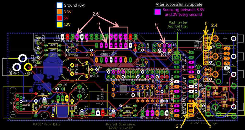
Someone else recently had issues with the 3.3v not being proper and I made the below diagram to trace the 3.3v path around the board a bit.
hm-424 (3.3v).jpg

The Y in the yellow line is the output of the 3.3v regulator, from there the 3.3v does bounce back and forth through traces on both sides of the board to reach the vairous points on the board.

The four pins where you note the 3.3v is lacking are actually the probe inputs. Would seem unlikely that low voltages there would cause the ATMega not to flash, unless there was something shorting out the 3.3v line there and lowering the VCC voltage for the ATMega.

The pins where the voltage should be bouncing would only start bouncing after the ATMega is programmed, so it seems she hasn't been flashed yet still...

Pins 7+20 are the VCC pins on the ATMega where the 3.3v power is supplied to the chip to make it operate.

Pins 8+22 are the GND for the ATMega

Pins 1,2,3 17,18,19 on the ATMega are the ones that connect to the rPi header to communicate between the rPi and the ATMega.

You will need proper 3.3v on the VCC pins and proper Gnd on the ATMega, then need the above 6 pins to connect to the rPi header. Here is the order in which they connect.

ATMega-----------rPi Header
------------------1, 8, 14, 15, 17, 22 (gnd)
1---------------------6
2---------------------20
3---------------------18
19--------------------3
18--------------------5
17--------------------7

So you can check continuity from the ATMega chip LEGS right through to the rPi (with POWER OFF) to be sure those connections are all present.

Although you have to keep in mind that you sparked something previously and suspect you might have damaged the LCD. So I suggest you not judge what is happening by what you see on the LCD at this point because we can't be sure it is still working. So, connect to the rPi via wired LAN or WiFi if possible, make sure your have the proper probe presets selected and see if the web UI is registering temperatures now....

With all the above verified, if you do not see temps on the web UI then it seems your ATMega is still not flashed. At this point you might want to connect a display to the rPi HDMI and watch it boot and see what is going on there. There is a command you can use to tell the rPi to force flash the ATMega, even though the HM SHOULD see the blank ATMega and flash it, worth a try to manually flash it and see what linkmeter reports.
 
Last edited:
Thanks again, Ralph.

I checked all the 3.3 points along your line in the image and they all check out.

All of the grounds on the ATMega and rPi header are good. EDIT: I take that back. Your note says rPi header pin 19 is a ground. I don't get a ground there. When I reference that pin against the 12v, I get .01v.

I have the appropriate continuity between the ATMega and rPi header - it took me a long time to figure out how the rPi header pins were numbered.

And I do see temperatures when I connect to the WiFi. They are way out of whack (unless it's 170 degrees in my house), but they are there.

So close, yet so far.

Thanks!
 
Last edited:
Alright, it almost sounds like the ATMega is flashed now.... So make sure you have the proper preset selected for each probe, and if the temps do not come in line then look carefully at all the solder work on the probe jack side of the ATMega. If I recall correctly I think there was some pretty poor soldering there but I didn't raise it as an issue initially because I didn't think it would prevent the ATMega from flashing.

I assume the display is not showing you anything still or you would have said something about it, and that you have tried (again) to adjust the contrast pot on the HM board.

One step at a time, we'll get her working!
 
On the rPi gnd at pin 19 on the rPi header, that was actually my mistake. Looking at the schematic it is pin 15 and 17 that are gnd (not 17 and 19) So you seem good on all that stuff.

I will correct that above in case anyone else reference this thread.
 
I reflowed the joints on the right side of the board and got much better readings from the probes. The connectors for my thermocouple haven't come in yet, so I didn't try that. I tried port 1 and 2 - 2 was reading about 10 degrees higher than 1 even when I swapped the probes around.

I didn't get time to re-check those voltages, so that's on my list for tonight.

My voltages still aren't bouncing on the points where they should be.
 
To verify that we are getting actual readings from the probes, hold one in your hand and let it warm up, see if the temp tracks up and down when you hold then release the probe.
If you've got that then you are getting close to where you want to be.
 
Yes, sorry, I should have mentioned that. I grabbed the probes and they did temp up and down when released. I also touched one to the upper barrel of my soldering iron as it cooled and the temp spiked up.


Back
Top