Steve_M
TVWBB Guru
I'll start here since there's a few pretty knowledgeable folks that might be able to help me out.
I've got a few SMD capacitors that are now on the loose, meaning that they're sitting on my bench, and I have no idea of what value they are. Some research has led me to info on RC circuits and that I should be able to determine the pf value of the caps with the help of a signal generator and an o-scope. Good news, I happen to be in possession of a Syscomp Circuit Gear.
The problem I'm running into is that I'm not getting any useful readings when the RC circuit is created.
I've got the Circuit Gear signal generator sending a 1K square wave and can see it on the o-scope
My circuit:

Diagram 1: Things look OK
Probe A connected to the signal generator
Probe B connected to the other side of the 10K resistor. No capacitor in the circuit yet.

Diagram 2: With the 200uf capacitor in the circuit, it looks as if the capacitor is basically grounding out the circuit and no matter how much I try to zoom in, I don't see any indication of the capacitor being charged and discharged

Any ideas on what's up?
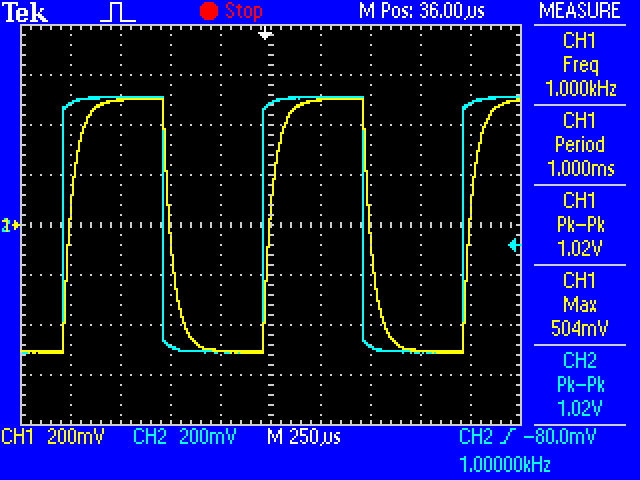
I was hoping to see something like this:
I've got a few SMD capacitors that are now on the loose, meaning that they're sitting on my bench, and I have no idea of what value they are. Some research has led me to info on RC circuits and that I should be able to determine the pf value of the caps with the help of a signal generator and an o-scope. Good news, I happen to be in possession of a Syscomp Circuit Gear.
The problem I'm running into is that I'm not getting any useful readings when the RC circuit is created.
I've got the Circuit Gear signal generator sending a 1K square wave and can see it on the o-scope
My circuit:
Diagram 1: Things look OK
Probe A connected to the signal generator
Probe B connected to the other side of the 10K resistor. No capacitor in the circuit yet.
Diagram 2: With the 200uf capacitor in the circuit, it looks as if the capacitor is basically grounding out the circuit and no matter how much I try to zoom in, I don't see any indication of the capacitor being charged and discharged
Any ideas on what's up?
I was hoping to see something like this:
