HM4.3 Erratic Behavior


David Dellanave

New member
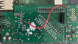
Hi guys, just built a HM 4.3 and I am stumped. When I initially powered it up I had some smoke coming from what looked like near the trace areas around the 5V power supply. I removed, re-soldered, double checked that, and then I was getting smoke and heat on the trace between pins 2 & 3 of the MOSFET on the back side of the board, and the inductor was heating up. Same thing, after some de/re-soldering that seemed to be straightened out. Really bothers me that I never found a CAUSE, but at least it seemed like it was fixed. Best I can tell I have clean 12V power, 5V at the right places, and 3.3V at the right places.

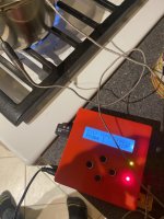
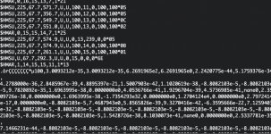
But my HM is totally erratic. Probe readings are all over the place on both thermistor and thermocouple. The screen worked, with some gibberish characters, for a bit, now it's not working. Sometimes I can re-flash the Atmel, bust most of the time it says AVR fuses error. I've tried with & without the LCD board, and I've tried with and without the raspberry pi. I've re-flowed everything, checked and triple checked for shorts and stray solder. I've tried a brand new Atmel, with no change. Right now I have the MOSFET completely removed.

Could the 5V power supply be damaged in such a way that it would create totally erratic behavior?

I am stumped. Any suggestions on things to check before I start replacing components one at a time?
 
I've spent all night tinkering with this. I pulled out the OKI-78SR and powered the board only from the raspberry pi, which from reading posts on this board and tracing the circuit seems like it should work. I even installed a brand new atmega328p and I was able to flash that a couple times, and then that stopped working. It almost seems like I am burning up Atmegas, but I don't know how that would be possible.
 
Posting this update as a troubleshooting log as much as anything.

At this point I'm totally unable to flash the m328p. Right now I've got the HM being powered from the raspberry pi plugged into a wall wart, and the OKI-78SR installed, but the result was the same with it removed from the circuit. I've got

continuity, and no shortse:
RPI MOS<->HM MOS
RPI MIS<->HM MIS
RPI SCK<->HM SCK
RPI GPIO 25<->HM RST

3.3V at VCC & AVC. GND continuity.

On another debugging thread it was suggested to check voltages at PIT,F01 etc. I have erratic voltages at PIT, F01, F02, F03, somewhere around 2.5V but they change.

The only indication of anything working is that I know RST is being pulled low because I'll see the LEDs and LCD backlight blink for a split second when avrdude runs.

I've got another RPI 3B+ here but for some reason it will absolutely not boot the heatermeter image. Boots fine with raspbian, and I even tried swapping the bootcode.bin and start.elf files but it won't boot it. Anyway I booted that RPI into raspbian just to try to use it to flash the atmel with avrdude, and the SPI doesn't work to flash the atmel from there either.

I am utterly stumped, and at this point I'm not even sure that I've got a good m328p because it seems like I am burning them up somehow.
 
That is certainly the definition of erratic behavior, David! I'm not sure what would cause those symptoms and you've done a great job of troubleshooting by eliminating various subsystems to narrow it down. Unfortunately, I can't think of any reason you'd see such a varied set of indicators. If the probes are showing voltages other than 3.3V when nothing is plugged in, that would seem to indicate something wong with the 3.3V supply, since they're just pulled up to the supply rail.

You might want to check with the power off and no Pi connevcted and check for low resistance between 12V and GND, 5V, 3.3V, and even the SCK, MOS, MIS, G25 signal lines. I recently soldered a HeaterMeter where I managed to somehow get a wisp of solder between 12V and SCK that was under the LCD riser connector. The only way I found it was that there was a short between 12V and SCK, and 2.2K ohms between the right MOSFET pin and SCK. I swapped out 5 parts just trying to figure it out before I pulled the LCD conector off and the short went away. That's probably not the case in your scenario, but measuing the resistance between signal lines and power rails might start to point you in the right direction.

I can also take a look at your boards if you want to ship them to me. I can't guarantee I'll be able to repair them given such a strange set of symptoms.but I'd only charge for shipping and cost for any components I'd replace. Send me a private message if you'd like to go that route and I'll give you my address.
 
@Bryan Mayland Your offer to take a look is very kind, but I'll give it some more debugging effort before giving up. I've got some new parts on the way that I'll wait for, and then I'll try to isolate the components even more. I'm pretty sure I burned up 3 Atmels, which I can't even figure out how that would happen, but I'm going to modify a DIP socket so that only the flashing pins are connected and then stage it back in to each feature and see if I can figure out where the issue is. Obviously there was an issue, or I wouldn't have had smoke in the first place, and the 3.3V regulator is the only one I didn't replace.

What's odd is that after I sorted out the smoke, the HM worked pretty OK at first other than the erratic probe readings. But then the gibberish on the LCD got to be more and more before it finally stopped working at all. There must be a wisp of a short somewhere that I haven't been able to find.

I'll definitely take a look between the voltage and signal lines. Thanks!
 
@Bryan Mayland A new Atmel has me somewhat back in action, but I've still got the board trimmed down in terms of component systems. Probe readings are all totally erratic.

What could possibly cause the voltages I'm seeing at the probe points? Right now I've got the 3.3V regulator removed, and the 3.3 rail jumpered to the 3.3V of the Raspberry Pi. MOSFET, MCP, and OKI are all removed right now.

Along the 3.3V rail at each probe jack, including the SMD cap that is the input for the TC circuitI have ~3.3V. They vary slightly, but around 3.2-3.

If I trace that to the probe-side leg of the 100k resistors, I still have around the same voltage.

BUT on the other side of the resistor, the voltage is wildly different. 2.5V on F01-F02 and around 1V on F03 but that moves around. I even pulled out those resistors and them soldered them back in.

What am I missing? This has to be something obvious that I am not seeing.

IMG_7500.JPG
 
What about if you remove the atmega chip, does the voltage still vary at the F1-F3 points where the atmega would be? You've really got me scratching my head too, because based on what you're saying, the microcontroller is somehow pulling current from the ADC inputs. That might indicate a bad connection on AGN, AVC, or ARE. AVC should be a dead short to 3.3V, AGN a dead short to GND. ARE should not be connected to anything at all without the microcontroller installed, but also check the grounds on both those two capacitors (by the number 35473D on your photo, but the pin further from the microcontroller) to make sure they have a good GND connection.
 
What about if you remove the atmega chip, does the voltage still vary at the F1-F3 points where the atmega would be? You've really got me scratching my head too, because based on what you're saying, the microcontroller is somehow pulling current from the ADC inputs. That might indicate a bad connection on AGN, AVC, or ARE. AVC should be a dead short to 3.3V, AGN a dead short to GND. ARE should not be connected to anything at all without the microcontroller installed, but also check the grounds on both those two capacitors (by the number 35473D on your photo, but the pin further from the microcontroller) to make sure they have a good GND connection.

Yes, with the Atmega removed I still have weird voltages. 3.3 at PIT & F01, 2.64 at F02, and 1.2 at F03.

Grounds on both caps for AVC & ARE: good, 0.0 resistance
Good 3.3V at AVC, and good ground at AGN.

I'm racking my brain trying to understand or SEE what could cause these spurious voltages.

Bottom of the board for reference (my soldering looked better before I had to desolder half the board):
 

Attachments

  • IMG_7503.JPG
    IMG_7503.JPG
    170.2 KB · Views: 6
At the risk of sending you on a wild goose chase, the following thread a user reported an intermittent short on one of the 0.1uF caps. You might try pulling those caps and see it it corrects issue.

 
What is the opposite of Occam's Razor?

I desoldered my DIP and now all my voltages are as expected.

What do we want to bet everything works perfectly once I solder in a new DIP socket?
 
I desoldered my DIP and now all my voltages are as expected.
I'm making a pretty disapproving face right now at your DIP socket. Hhhhhhoowwww? I mean... how would... do some of the pin positions show as connected to others? It is nuts because they're not shorted together, they have some sort of resistance together. Did they make the socket out of conductive plastic?! This issue is just really flippin' bizarre, but I hope you've found the culprit.
 
Well, this is going to be one of those unsatisfying cases of not knowing the exact issue. The problem came back after I installed the DIP. I did revisit the soldering on the little caps, and it seems like *maybe* one or two of the caps had been pushed in so far that the insulation was covering the leg so perhaps it wasn't in good contact with the top trace of the PCB.

End result though, is a very happy heatermeter. Thanks for the extra time spent debugging.
 

Attachments

  • IMG_7509.JPG
    IMG_7509.JPG
    130.3 KB · Views: 2
@Bryan Mayland I spoke too soon, and the problems are maybe even more bizarre. I let the HM run overnight as sort of a burn-in, and at some point it stopped working again.

Right now in terms of debugging I've got the m328p inserted into a DIP I modified so that only the critical pins to run the Atmega are connected, as well as Tx/Rx to the pi.

Reading directly from the serial port, it will kick out 1Hz updates pretty nicely for a little while... and then it just starts to sporadically stop. Come back for a few. Stop again. In fact on the latest one I saw pop up, it was gibberish for the first time:

$HMSU,225,34.3,407.5,U,U,100,12,0,100,100*06
$HMSU,225,38.4,570.2,U,U,�'L�)�b�b���b���R�
)�

What in the hell? Bad crystal? At this point there's almost nothing I haven't already replaced.

I wish I could swap in another RPi to see if I've been chasing phantom issues this whole time, but my other RPi 3B+ won't boot the image.
 
Argh man, I don't even know. This is like some sort of enigma, and I am wondering if maybe that board had a curse put on it that causes it to defy all reasoning. Would you be upset if I sent you a whole new base board kit to try? I mean you'll have to solder it all over again but at this point I feel like maybe we just need to give it the Heisman pose and pretend none of this happened. It wouldn't go out until Thursday, but (I'm just sitting here shaking my head constantly in disbelief at how random this all is) I mean golly how is this happening?
 
@Bryan Mayland I am not opposed to it, and that's very kind of you, but I also don't want to be a bother. Right now I've got it hooked up to my Mac with literally just the required pins for the Atmel and the serial pins, and a 3-wire jumper to an RS232 to TTL adapter, powering it from a pretty nice DC power supply I have. Even with ONLY those connected, it will suddenly stop outputting to serial. Sometimes it comes back a little while later, sometimes it doesn't. No rhyme or reason to any of it. This is how the most recent episode went. I am utterly baffled.
 

Attachments

  • Untitled_0.jpg
    Untitled_0.jpg
    149.8 KB · Views: 4


Back
Top