RyanBama
New member
Hi all, I'm creating this thread because i'm wanting to use simply use heater meter for the webui and thermometer functionality. I'm having some difficulty understanding how to wire up the arduino to the raspberry pi. There are many pictures and diagrams using the heatermeter "oem" (for lack of a better word) hardware but i can't find something on just using a pi and an arduino. I've searched the thread archive but perhaps my search-foo for this board is lacking. Any direction would be appreciated.
The man himself, Bryan gave me the following direction and i've set up what i believe to be a correct wiring configuration.
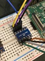
I purchased the following level shifter:
https://www.amazon.com/gp/product/B07LG646VS/?tag=tvwb-20
I've soldered the voltage level shifter together and plugged it into my breadboard and wired it up as i understood it to work. However when i'm in the linkmeter UI there is no device found and i get no input on thermometers. (granted i have no thermometers currently plugged in, i'd just expect wild temperature reading in the ui. Is that correct?
quickfacts:
The man himself, Bryan gave me the following direction and i've set up what i believe to be a correct wiring configuration.
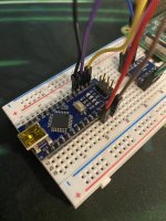
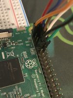
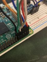
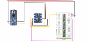
All you need to do is wire RX, TX, and GND from the Nano to the Pi's TX, RX, GND respectively. The Arduino Nano has 5V I/O though so you'll need to run it through a level shifter to keep from frying the Pi. The Arduino can be powered from the 5V pins on the Pi as well (plugged into the 5V pin on the Nano, not VIN).
I purchased the following level shifter:
https://www.amazon.com/gp/product/B07LG646VS/?tag=tvwb-20
I've soldered the voltage level shifter together and plugged it into my breadboard and wired it up as i understood it to work. However when i'm in the linkmeter UI there is no device found and i get no input on thermometers. (granted i have no thermometers currently plugged in, i'd just expect wild temperature reading in the ui. Is that correct?
quickfacts:
- Linkmeter device is an arduino nano
- voltage level shifter (see amazon link above on model)
- raspberry pi 3 v1.2
- Manually flashed heatermeter.hex to arduino using windows command prompt and command built using avrdude that comes with arduino software 1.8.13.
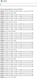
- Flash was successful and when observing the output from the arduino (see output screenshot) it looks to be functioning as expected.
- I am powering the arduino off the pi.
- Have confirmed 5v on the HV side of level shifter and 3v on the 3v side of the level shifter going to the pi.
Attachments
Last edited:
